Mohammad H. Sadraey - Introduction to UAV Systems
Здесь есть возможность читать онлайн «Mohammad H. Sadraey - Introduction to UAV Systems» — ознакомительный отрывок электронной книги совершенно бесплатно, а после прочтения отрывка купить полную версию. В некоторых случаях можно слушать аудио, скачать через торрент в формате fb2 и присутствует краткое содержание. Жанр: unrecognised, на английском языке. Описание произведения, (предисловие) а так же отзывы посетителей доступны на портале библиотеки ЛибКат.
- Название:Introduction to UAV Systems
- Автор:
- Жанр:
- Год:неизвестен
- ISBN:нет данных
- Рейтинг книги:5 / 5. Голосов: 1
-
Избранное:Добавить в избранное
- Отзывы:
-
Ваша оценка:
Introduction to UAV Systems: краткое содержание, описание и аннотация
Предлагаем к чтению аннотацию, описание, краткое содержание или предисловие (зависит от того, что написал сам автор книги «Introduction to UAV Systems»). Если вы не нашли необходимую информацию о книге — напишите в комментариях, мы постараемся отыскать её.
The latest edition of the leading resource on unmanned aerial vehicle systems
A thorough introduction to the history of unmanned aerial vehicles, including their use in various conflicts, an overview of critical UAV systems, and the Predator/Reaper A comprehensive exploration of the classes and missions of UAVs, including several examples of UAV systems, like Mini UAVs, UCAVs, and quadcopters Practical discussions of air vehicles, including coverage of topics like aerodynamics, flight performance, stability, and control In-depth examinations of propulsion, loads, structures, mission planning, control systems, and autonomy Introduction to UAV Systems
Design of Unmanned Aerial Systems
Introduction to UAV Systems
Introduction to UAV Systems — читать онлайн ознакомительный отрывок
Ниже представлен текст книги, разбитый по страницам. Система сохранения места последней прочитанной страницы, позволяет с удобством читать онлайн бесплатно книгу «Introduction to UAV Systems», без необходимости каждый раз заново искать на чём Вы остановились. Поставьте закладку, и сможете в любой момент перейти на страницу, на которой закончили чтение.
Интервал:
Закладка:
Figures 3.6and 3.7show two curves for each coefficient. Each curve is for a specified Reynolds number ( R ). The NASA database contains data for more than two Reynolds numbers, but Figures 3.6and 3.7reproduced only R = 3.0 × 10 6and R = 8.9 × 10 6. The two moment curves lie nearly on top of each other and are hardly distinguishable.
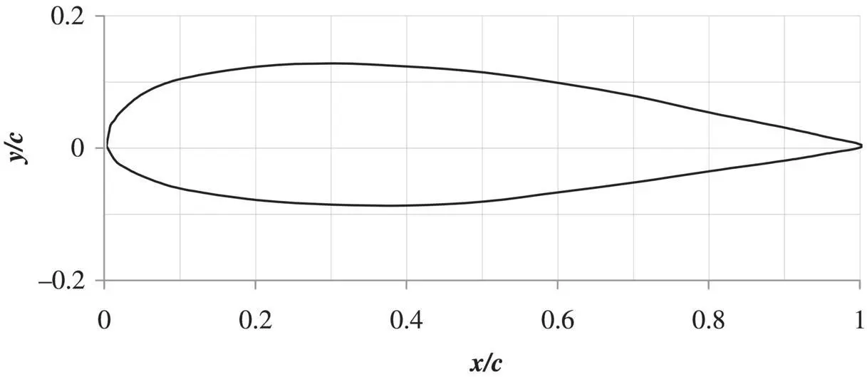
Figure 3.5 NACA 23021 airfoil profile
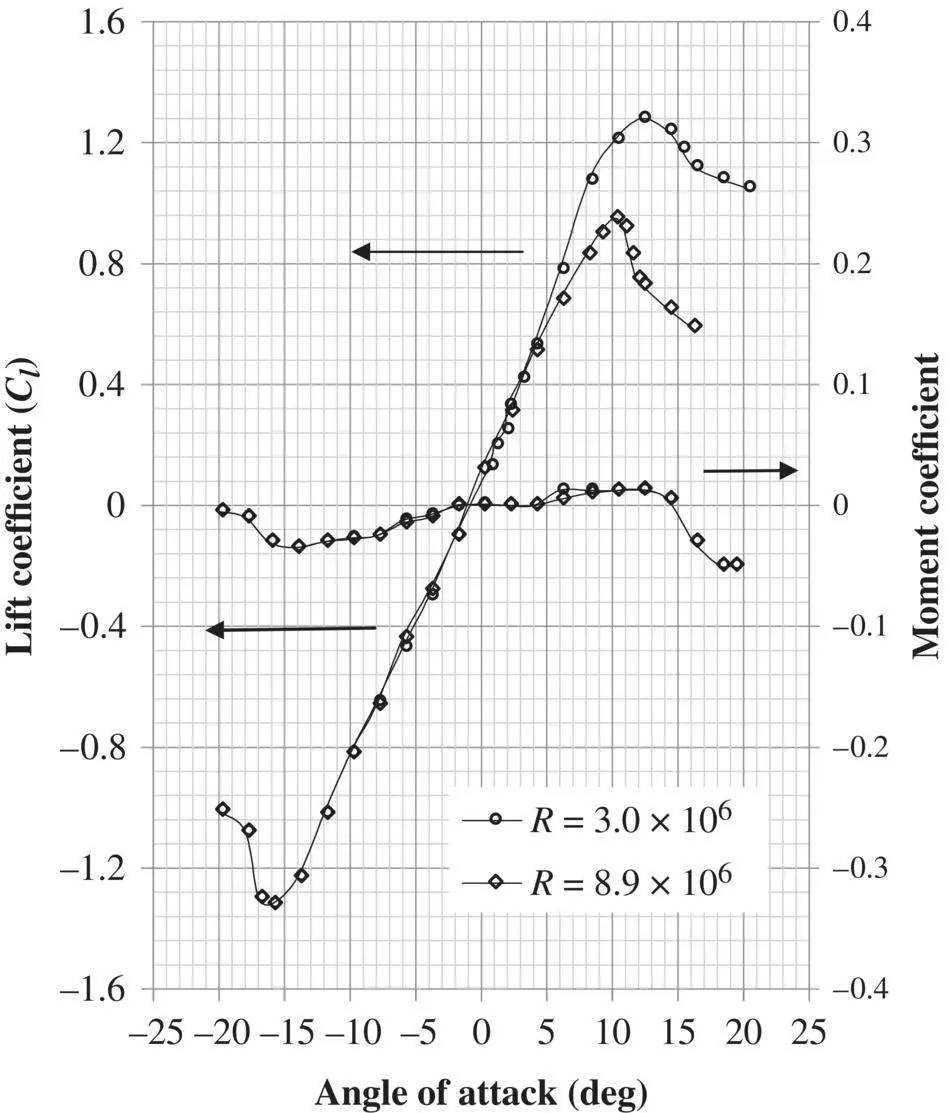
Figure 3.6 NACA 23021 airfoil coefficients versus angle of attack
The NASA LRN 1015 (NASA TM 102840) airfoil is used on the Northrop Grumman RQ‐4 Global Hawk (see Figure 1.4) wing. The airfoil maximum thickness is 15.2% at 40% chord, and its maximum camber is 4.9% at 44% chord.
The airfoils used on the MQ‐1 Predator (see Figure 11.1) wing is a proprietary material of General Atomics. However, it is estimated that the airfoil maximum thickness is 10% at 26.6% chord, and its maximum camber is 3.4% at 45.1% chord. The airfoil has a high camber, which provides the desired aerodynamic performance at high Reynolds numbers.
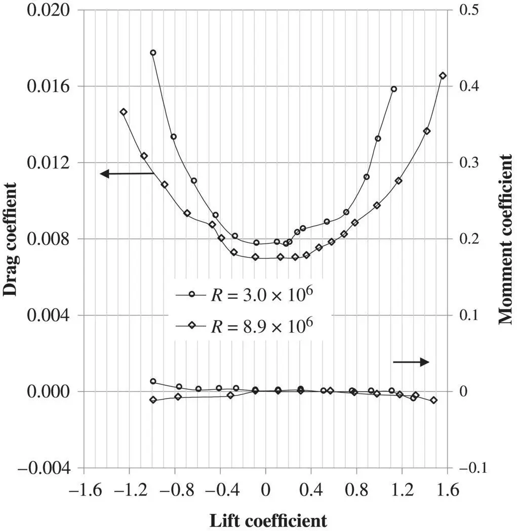
Figure 3.7 NACA 23021 airfoil coefficients versus lift coefficient
With the progress of the science of aerodynamics, there is a variety of techniques and tools to accomplish the time‐consuming job of calculating lift and drag. A variety of tools and software based on aerodynamics and numerical methods have been developed in the past decades. A number of CFD 1 Software packages based on Navier‐Stokes equations, the vortex lattice method, and thin airfoil theory are available in the market. The application of such software packages, which is expensive and time‐consuming, at this early stage of wing design seems un‐necessary.
3.5 Pressure Distribution
The aerodynamic forces on an object in the airflow (e.g., wing) can be calculated from pressure distribution around the object. The lift of a wing/tail is produced due to the pressure difference between the lower and upper surfaces. An airfoil‐shaped body moved through the air will vary the static pressure on the top surface and on the bottom surface of the airfoil.
In a positive cambered airfoil (at a positive angle of attack), the upper surface static pressure in less than ambient pressure, while the lower surface static pressure is higher than ambient pressure. This is due to the higher airspeed at the upper surface and the lower speed at the lower surface of the airfoil (see Figure 3.8). As the airfoil angle of attack increases, the pressure difference between the upper and lower surfaces will be higher.
The wing three‐dimensional (3d) lift coefficient ( C L) is directly a function of the airfoil two‐dimensional (2d) lift coefficient, c l. In turn, the variable c lis a function of variations of pressure coefficients on the upper and lower surfaces. For the case of a small angle of attack (less than 5 degrees), the 2d lift coefficient is calculated from
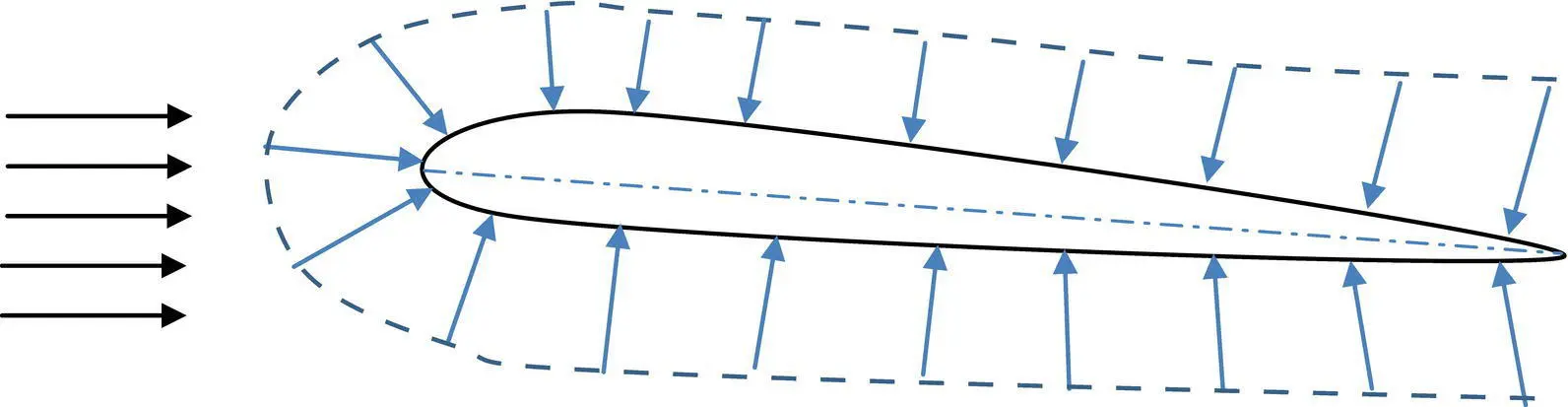
Figure 3.8 Pressure distribution for an airfoil section
(3.4) 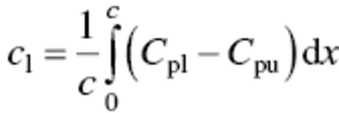
where C pland C puare pressure coefficients at the lower and upper surfaces respectively, and c is the airfoil chord. Thus, the lift is produced due to the pressure difference between the lower and upper surfaces of the wing/tail. References such as [8, 10, and 11] provide techniques to determine the pressure distribution around any lifting surface such as the wing. The variations of lift coefficient versus angle of attack are often linear below the stall angle. The UAVs are usually flying at an angle of attack below the stall angle (about 15 degrees).
The Northrop Grumman X‐47B ( Figure 3.9) an experimental unmanned combat air vehicle (UCAV) has provisions for various payloads such as EO/IR/SAR/GMTI. Its aerodynamic design allows for a maximum speed of Mach 0.9+ and a range of 3,900 km. This UCAV with a blended wing‐body tailless configuration, a maximum takeoff weight of 44,567 lb (mass of 20,215 kg), and a wing span of 62.1 ft (18.9 m) is equipped with a single turbofan engine.
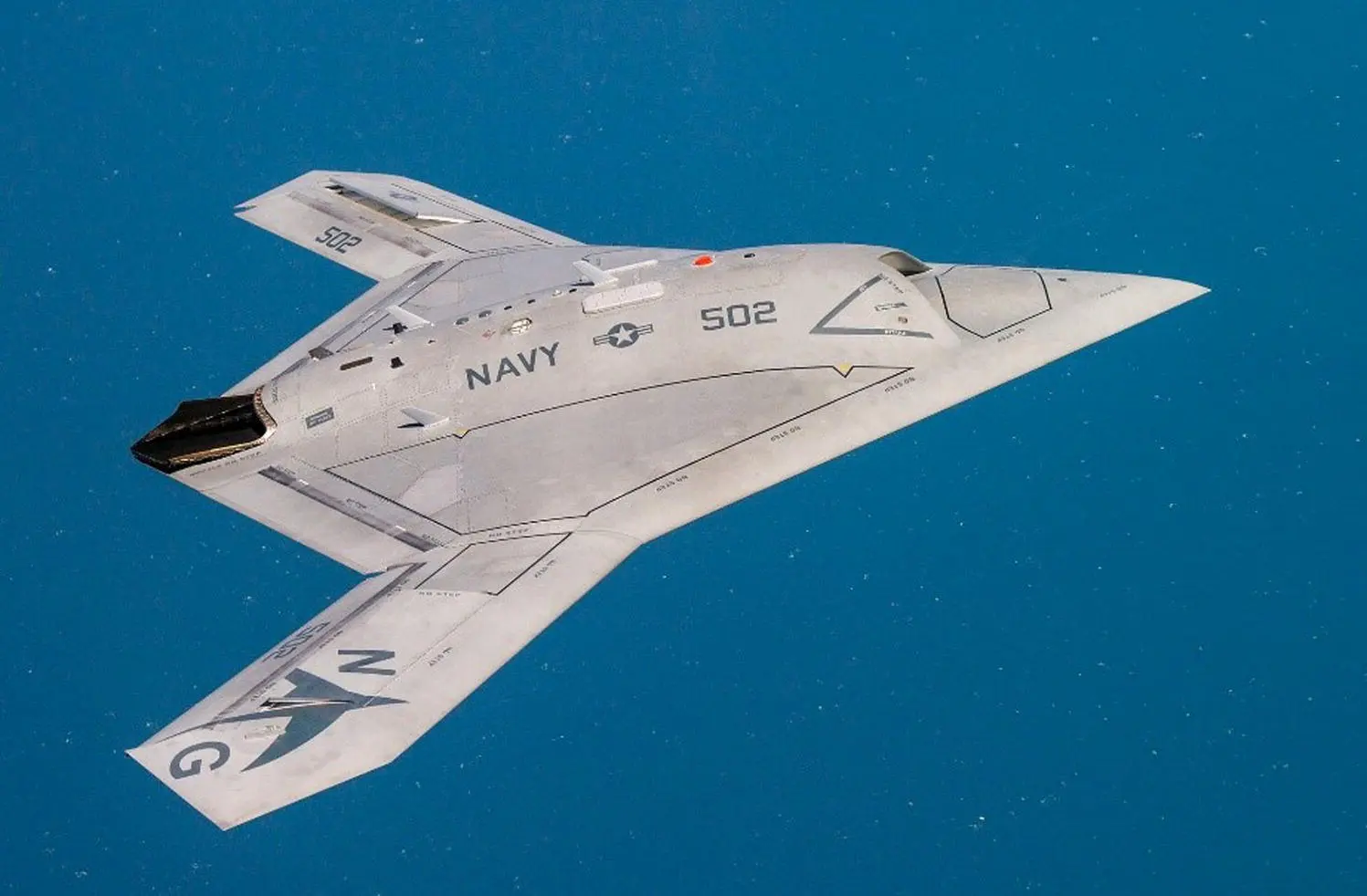
Figure 3.9 Northrop Grumman X‐47B UCAV
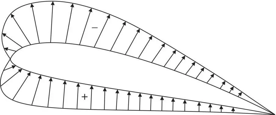
Figure 3.10 Net pressure distribution over an airfoil
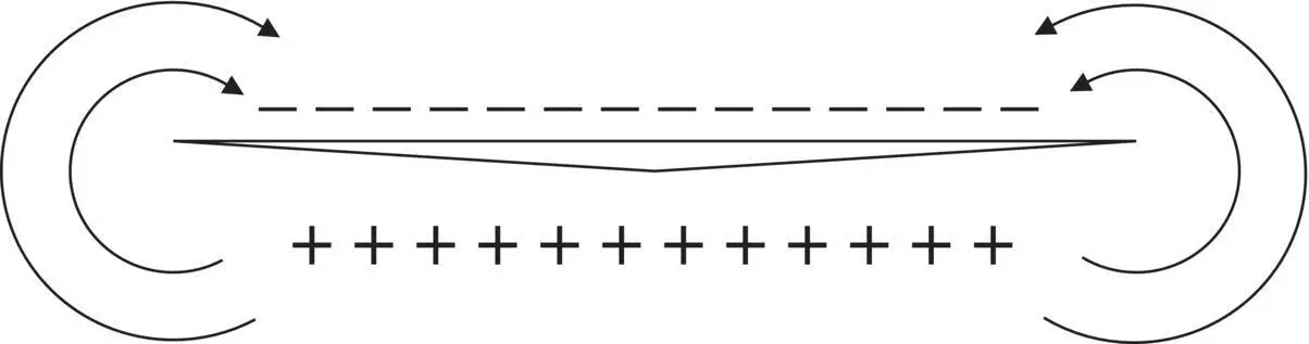
Figure 3.11 Spanwise pressure distribution around a 3d wing
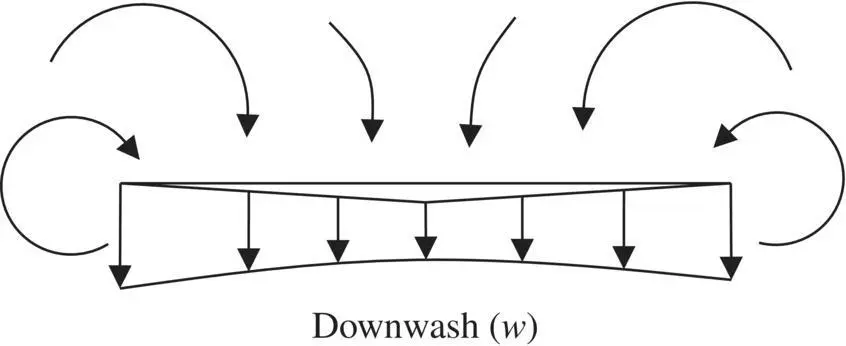
Figure 3.12 Downwash
Consider the net pressure distribution about an airfoil, as shown in Figure 3.10. It is apparent that a wing would have positive pressure on its underside and negative (in a relative sense) pressure on the top. This is shown in Figure 3.11as plus signs on the bottom and minus signs on the top as viewed from the front or leading edge of the wing.
Such a condition would allow air to spill over from the higher pressure on the bottom surface to the lower pressure on the top, causing it to swirl or form a vortex. The downward velocity or downwash onto the top of the wing created by the swirl would be greatest at the tips and reduced toward the wing center, as shown in Figure 3.12.
Aerodynamics textbooks (e.g., Reference [8]) are a good source to consult for information about mathematical techniques for calculating the pressure distribution over the wing and for determining the flow variables.
3.6 Drag Polar
Another important concept concerning the three‐dimensional air vehicle is what is known as the aircraft drag “polar,” a term introduced by Eiffel many years ago, which is a curve of C Lplotted against C D. A typical airplane drag polar curve is illustrated in Figure 3.13.
The drag polar will later be shown to be parabolic in shape and define the minimum drag (or zero‐lift drag), C Do, or drag that is not attributable to the generation of lift. A line drawn from the origin and tangent to the polar gives the minimum lift‐to‐drag ratio that can be obtained. It will also be shown later that the reciprocal of this ratio is the tangent of the power‐off glide angle of an air vehicle. The drag created by lift or induced drag is also indicated on the drag polar.
Читать дальшеИнтервал:
Закладка:
Похожие книги на «Introduction to UAV Systems»
Представляем Вашему вниманию похожие книги на «Introduction to UAV Systems» списком для выбора. Мы отобрали схожую по названию и смыслу литературу в надежде предоставить читателям больше вариантов отыскать новые, интересные, ещё непрочитанные произведения.


Обсуждение, отзывы о книге «Introduction to UAV Systems» и просто собственные мнения читателей. Оставьте ваши комментарии, напишите, что Вы думаете о произведении, его смысле или главных героях. Укажите что конкретно понравилось, а что нет, и почему Вы так считаете.