Anthony R. West - Solid State Chemistry and its Applications
Здесь есть возможность читать онлайн «Anthony R. West - Solid State Chemistry and its Applications» — ознакомительный отрывок электронной книги совершенно бесплатно, а после прочтения отрывка купить полную версию. В некоторых случаях можно слушать аудио, скачать через торрент в формате fb2 и присутствует краткое содержание. Жанр: unrecognised, на английском языке. Описание произведения, (предисловие) а так же отзывы посетителей доступны на портале библиотеки ЛибКат.
- Название:Solid State Chemistry and its Applications
- Автор:
- Жанр:
- Год:неизвестен
- ISBN:нет данных
- Рейтинг книги:4 / 5. Голосов: 1
-
Избранное:Добавить в избранное
- Отзывы:
-
Ваша оценка:
Solid State Chemistry and its Applications: краткое содержание, описание и аннотация
Предлагаем к чтению аннотацию, описание, краткое содержание или предисловие (зависит от того, что написал сам автор книги «Solid State Chemistry and its Applications»). Если вы не нашли необходимую информацию о книге — напишите в комментариях, мы постараемся отыскать её.
A comprehensive treatment of solid state chemistry complete with supplementary material and full colour illustrations from a leading expert in the field. Solid State Chemistry and its Applications, Second Edition
Student Edition
Significant updates and new content in this second edition include:
A more extensive overview of important families of inorganic solids including spinels, perovskites, pyrochlores, garnets, Ruddlesden-Popper phases and many more New methods to synthesise inorganic solids, including sol-gel methods, combustion synthesis, atomic layer deposition, spray pyrolysis and microwave techniques Advances in electron microscopy, X-ray and electron spectroscopies New developments in electrical properties of materials, including high Tc superconductivity, lithium batteries, solid oxide fuel cells and smart windows Recent developments in optical properties, including fibre optics, solar cells and transparent conducting oxides Advances in magnetic properties including magnetoresistance and multiferroic materials Homogeneous and heterogeneous ceramics, characterization using impedance spectroscopy Thermoelectric materials, MXenes, low dimensional structures, memristors and many other functional materials Expanded coverage of glass, including metallic and fluoride glasses, cement and concrete, geopolymers, refractories and structural ceramics Overview of binary oxides of all the elements, their structures, properties and applications Featuring full color illustrations throughout, readers will also benefit from online supplementary materials including access to CrystalMaker® software and over 100 interactive crystal structure models.
Perfect for advanced students seeking a detailed treatment of solid state chemistry, this new edition of
will also earn a place as a desk reference in the libraries of experienced researchers in chemistry, crystallography, physics, and materials science.
Solid State Chemistry and its Applications — читать онлайн ознакомительный отрывок
Ниже представлен текст книги, разбитый по страницам. Система сохранения места последней прочитанной страницы, позволяет с удобством читать онлайн бесплатно книгу «Solid State Chemistry and its Applications», без необходимости каждый раз заново искать на чём Вы остановились. Поставьте закладку, и сможете в любой момент перейти на страницу, на которой закончили чтение.
Интервал:
Закладка:
1.18.3 Point symmetry of molecules: general and special positions
The relationships between point symmetry and structure are best illustrated by examples of small molecules. The methylene dichloride molecule, CH 2Cl 2, Fig. 1.58, possesses (i) a single 2‐fold axis which bisects the H–С–H and Cl–С–Cl bond angles and (ii) two mirror planes (a). The 2‐fold axis is parallel to the line of intersection of the mirror planes. These symmetry elements may be represented as in (b), in which the 2‐fold axis is perpendicular to the plane of the paper and the mirror planes appear in projection as horizontal and vertical lines. From inspection of Fig. 1.55, it is seen that CH 2C1 2belongs to point group mm 2. However, the number of equivalent positions in mm 2 is four (c), which does not appear to tally with the realities of the CH 2CI 2molecule. Thus, if we place a H atom at one equivalent position, there should be only two possible equivalent positions in the molecule, as there are only two H atoms present. This apparent anomaly is resolved by letting the equivalent positions in Fig. 1.55(c) lie on the vertical mirror plane instead of to either side of the mirror. This yields the arrangement shown in Fig. 1.58(c), which now has only two equivalent positions. Thus, positions 1 and 2 in Fig. 1.55(c) become the single position A in Fig. 1.58(c). We can now distinguish between the general equivalent positions of a point group and the special equivalent positions; the latter arise when the general positions lie on a symmetry element such as a mirror plane or rotation axis. Thus, A and В in Fig. 1.58(c) are both special positions.
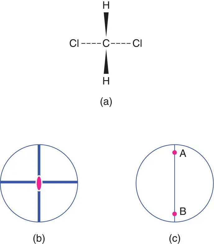
Figure 1.58 The symmetry of the methylene dichloride molecule, CH2Cl2, point group mm2.
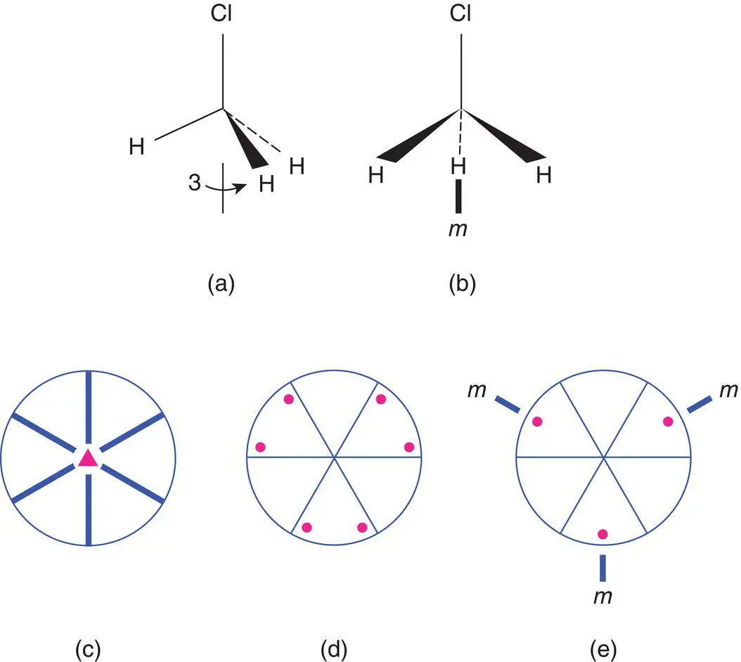
Figure 1.59 The symmetry of the methyl chloride molecule, CH3Cl, point group 3m.
As a second example, the point symmetry of the methyl chloride molecule, CH 3CI is shown in Fig. 1.59. The molecule possesses one 3‐fold axis along the direction of the С–Cl bond (a). It has no 2‐fold axes but has three mirror planes oriented at 60° to each other; one is shown in (b). The 3‐fold axis coincides with the line of intersection of the mirror planes. The symmetry elements are shown as a stereogram in (c) and by comparison with Appendix E, we see that the point group is 3 m . The six general equivalent positions in 3 m are given in (d). We again have the problem that there are more equivalent positions than possible atoms and this is overcome by allowing the general positions to lie on the mirror planes (e); the number of positions is thereby reduced to three.
1.18.4 Centrosymmetric and non‐centrosymmetric point groups
Of the 32 point groups, 21 do not possess a centre of symmetry. The absence of a centre of symmetry is an essential but not sufficient requirement for the presence in crystals of optical activity, pyroelectricity and piezoelectricity ( Chapters 8and 10). Optical activity is confined to 15 of the 21 non‐centrosymmetric point groups and piezoelectricity to 20 of these. This is of use in, for example, the search for new materials with piezoelectric activity; it is a waste of time trying to detect piezoelectricity in crystals whose point group is not among the 20 active groups! Crystallographers also make some use of the piezoelectric effect in structure determination. It is a considerable help in solving an unknown structure to know the space group at the outset. If a test for piezoelectricity is carried out with positive results, this limits the choice of space group to the non‐centrosymmetric ones. The absence of piezoelectricity does not necessarily mean, however, that the point group and space group are centrosymmetric.
1.18.5 Space groups
The combination of the 32 possible point groups and the 14 Bravais lattices (which in turn are combinations of the 7 crystal systems, or unit cell shapes, and the different possible lattice types) gives rise to 230 possible space groups. All crystalline materials, apart from those showing either quasisymmetry, Section 1.2.2, or those that possess a superstructure with a different, incommensurate periodicity to that of the sublattice, have a structure which belongs to one of these space groups. This does not, of course, mean that only 230 different crystal structures are possible. For the same reason, the human body (from its external appearance) is not the only object to belong to point group  teapots also do!
Space groups are formed by adding elements of translation to the point groups. The space symmetry elements – screw axes and glide planes – are derived from their respective point symmetry elements – rotation axes and mirror planes – by adding a translation step in between each operation of rotation or reflection, Section 1.2.5. A complete tabulation of all possible screw axes and glide planes and their symbols is not given here; instead, symbols are explained as they arise. We also discuss only a few of the simpler space groups; however, once the basic rules have been learned, by working through these examples, there should be no difficulty in understanding and using any space group. The interested reader is recommended to consult the authoritative International Tables for X‐ray Crystallography , Vol 1 (preferably an early edition as later additions contain extra material of relevance only to specialist crystallographers).
The written symbol of a space group contains between two and four characters. The first character is always a capital letter which corresponds to the lattice type: P, I, A , etc. The remaining characters correspond to some of the symmetry elements that are present. If the crystal system has a unique or principal axis (e.g. the 4‐fold axis in tetragonal crystals), the symbol for this axis appears immediately after the lattice symbol. For the remaining characters, there appear to be different rules for different crystal systems. As these rules are not essential to an understanding of space groups, they are not repeated here.
Space groups are usually drawn as parallelograms to represent the unit cell, with the plane of the parallelogram corresponding to the xy plane of the unit cell. By convention, Fig. 1.60(a), the origin is taken as the top left‐hand corner, with y horizontal, x downwards and the positive z direction out of the plane of the paper and pointing towards the reader. For each space group, two parallelograms are used, the left‐hand one gives the equivalent positions; the right‐hand one gives the symmetry elements. Let us see some examples. Each one introduces at least one new feature.
1.18.5.1 Triclinic P
This space group is primitive and centrosymmetric; it is shown in Fig. 1.60(b, c). The right‐hand diagram shows the symmetry elements: there are centres of symmetry (shown as small open circles) at the origin ( t ), midway along the a and b edges and in the middle of the С face (i.e. the face bounded by a and b ). Additional centres of symmetry, not shown, occur in the middle of the other faces, halfway along the с edge and at the body centre of the unit cell.
Читать дальшеИнтервал:
Закладка:
Похожие книги на «Solid State Chemistry and its Applications»
Представляем Вашему вниманию похожие книги на «Solid State Chemistry and its Applications» списком для выбора. Мы отобрали схожую по названию и смыслу литературу в надежде предоставить читателям больше вариантов отыскать новые, интересные, ещё непрочитанные произведения.


Обсуждение, отзывы о книге «Solid State Chemistry and its Applications» и просто собственные мнения читателей. Оставьте ваши комментарии, напишите, что Вы думаете о произведении, его смысле или главных героях. Укажите что конкретно понравилось, а что нет, и почему Вы так считаете.