Ernst Lueder - Liquid Crystal Displays
Здесь есть возможность читать онлайн «Ernst Lueder - Liquid Crystal Displays» — ознакомительный отрывок электронной книги совершенно бесплатно, а после прочтения отрывка купить полную версию. В некоторых случаях можно слушать аудио, скачать через торрент в формате fb2 и присутствует краткое содержание. Жанр: unrecognised, на английском языке. Описание произведения, (предисловие) а так же отзывы посетителей доступны на портале библиотеки ЛибКат.
- Название:Liquid Crystal Displays
- Автор:
- Жанр:
- Год:неизвестен
- ISBN:нет данных
- Рейтинг книги:4 / 5. Голосов: 1
-
Избранное:Добавить в избранное
- Отзывы:
-
Ваша оценка:
Liquid Crystal Displays: краткое содержание, описание и аннотация
Предлагаем к чтению аннотацию, описание, краткое содержание или предисловие (зависит от того, что написал сам автор книги «Liquid Crystal Displays»). Если вы не нашли необходимую информацию о книге — напишите в комментариях, мы постараемся отыскать её.
THE NEW EDITION OF THE GOLD-STANDARD IN TEACHING AND REFERENCING THE FUNDAMENTALS OF LCD TECHNOLOGIES
Liquid Crystal Displays — читать онлайн ознакомительный отрывок
Ниже представлен текст книги, разбитый по страницам. Система сохранения места последней прочитанной страницы, позволяет с удобством читать онлайн бесплатно книгу «Liquid Crystal Displays», без необходимости каждый раз заново искать на чём Вы остановились. Поставьте закладку, и сможете в любой момент перейти на страницу, на которой закончили чтение.
Интервал:
Закладка:
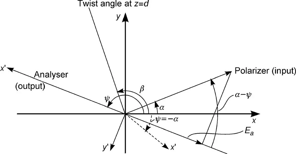
Figure 4.5Angles and coordinates for an STN display
and
(4.67) 
For
(4.68) 
Equations (4.66)and (4.67)yield
(4.69) 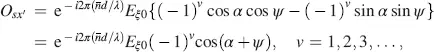
and
(4.70) 
Osx′ reaches its maximum
(4.71) 
for
(4.72) 
If the axis x ′ of the analyser is at an angle ψ = − α to the x -axis, the maximum intensity  passes the cell. For energy reasons the intensity in the y ′ -direction must be zero, which is met in Equation (4.70). The direction x ′ for maximum intensity is shown by dashed lines in Figure 4.5. The condition in Equation (4.68)for maximum intensity yields for a from Equation (4.64)
(4.73) 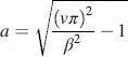
with the first realizable value for v = 2. For β = 3( π /2), we obtain the values
(4.74) 
From Equation (4.64), we calculate the thickness
(4.75) 
For λ = 550 nm, β = 3( π /2),  and Δ n 0.05 the thickness is d = 14.5 μm. As the thickness in Equation (4.75)is proportional to β , STN displays operate with thicker cells than regular TN displays.
The intensity passing the analyser at an angle ψ describes the normally white state, with the maximum for ψ = − α . If a high enough field is applied, the linear polarized light reaches the analyser at the angle α , resulting (according to Figure 4.5) in a component
(4.76) 
For α = π /4, and hence ψ = − α = π/ 4, we obtain E a= 0 independent of λ . This normally white state exhibits an excellent black state, and works with crossed polarizers.
For the optimum ψ = − α and the normally black state, the analyser has to be placed, due to Equation (4.70), in the y ′ -direction, which is for ψ = − α = − π /4 parallel to the polarizer. In this case, however, O syholds only for one wavelength in Equation (4.75). The white state after a field has been applied fully passes the analyser.
As the normally white state exhibits a black independent of wavelength, it is the preferred mode of operation.
If the large thickness of an STN cell is decreased, the transmission falls below optimum and some luminance is sacrificed, but a wider viewing angle is obtained. The reason for this will be explained in the chapter on compensation foils later.
The larger twist angle β in supertwist nematic LCDs has a pronounced effect on the transmitted luminance versus voltage curve in Figure 4.6by rendering the transition from the white state to the black state much steeper. As will be explained in Chapter 12, this enhanced steepness is required for addressing an STN cell with a larger number of lines without losing too much contrast. The increase in steepness with increased β is now explained phenomenologically. In the transition from, let’s say, the white state to the black state, the LC molecules have to be tilted by a torque stemming from the applied electrical field. They finally end up parallel to the field. A smaller torque is needed if the molecules exhibit a larger twist angle from layer to layer as the restoring force by the vertically neighbouring molecules becomes weaker. Hence, a smaller voltage is required to achieve the tilt angles.
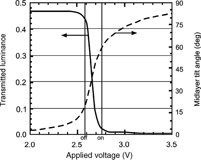
Figure 4.6Transmitted luminance and midlayer tilt versus the voltage across an STN cell with a twist of β = 240°, an off-voltage of 2.58V and an on-voltage of 2.75V for addressing 240 lines (Reproduced from Scheffer and Nehring, 1998 with permission of Annual Reviews.)
A calculation of this effect is based on fluid mechanics and liquid crystal continuum equations (Degen, 1980), where the mechanical parameters K 11, K 22and K 33, the dielectric constants ε ┴and ε ||, the pretilt angle at the orientation layers and, of course, the twist angle β and d / p play a role. The calculations are similar to the electro-optical investigations of TN cells in Section 4.1, because propagation matrices based on the mechanical properties are established for a sequence of twisted layers, and are finally multiplied.
Figure 2.12 shows that the tilt of the molecules is larger in the midlayer due to the restoring forces of the molecules anchored on top of the orientation layer. Figure 4.7depicts the midlayer tilt versus the voltage V LCacross the cell with twist angles β as a parameter. The larger is β , the greater is the slope of the curves. For β = 3 π /2(270°) the curve rises perpendicularly in the centre portion. For β greater than 270° the curves become double-valued, causing bistability and hysteresis. Therefore, the twist must not exceed 270°. STN cells use twists between 180° and 270°, where 240° is often encountered as the electro-distortional curves are steep, but sufficiently removed from bistability.
To sustain these large twists, chiral compounds have to be added. The chiral dopant imparts an intrinsic twist, given by d / p , to the helical structure. On the other hand, the twist angle is also imposed by the angular difference Φ Tof the rubbing directions. A matching of the two constraints requires d / p = Φ T/2 π . In practical STN cells d / p > Φ T/2 π is chosen, which compresses the helical structure in order to avoid the phenomenon of stripes. These stripes are generated if the condition that the local optic axis changes orientation only along the spatial coordinate perpendicular to the layer is not met (Nehring and Scheffer, 1990). They result in scattering of light, rendering the display unacceptable.
Читать дальшеИнтервал:
Закладка:
Похожие книги на «Liquid Crystal Displays»
Представляем Вашему вниманию похожие книги на «Liquid Crystal Displays» списком для выбора. Мы отобрали схожую по названию и смыслу литературу в надежде предоставить читателям больше вариантов отыскать новые, интересные, ещё непрочитанные произведения.


Обсуждение, отзывы о книге «Liquid Crystal Displays» и просто собственные мнения читателей. Оставьте ваши комментарии, напишите, что Вы думаете о произведении, его смысле или главных героях. Укажите что конкретно понравилось, а что нет, и почему Вы так считаете.