Ernst Lueder - Liquid Crystal Displays
Здесь есть возможность читать онлайн «Ernst Lueder - Liquid Crystal Displays» — ознакомительный отрывок электронной книги совершенно бесплатно, а после прочтения отрывка купить полную версию. В некоторых случаях можно слушать аудио, скачать через торрент в формате fb2 и присутствует краткое содержание. Жанр: unrecognised, на английском языке. Описание произведения, (предисловие) а так же отзывы посетителей доступны на портале библиотеки ЛибКат.
- Название:Liquid Crystal Displays
- Автор:
- Жанр:
- Год:неизвестен
- ISBN:нет данных
- Рейтинг книги:4 / 5. Голосов: 1
-
Избранное:Добавить в избранное
- Отзывы:
-
Ваша оценка:
Liquid Crystal Displays: краткое содержание, описание и аннотация
Предлагаем к чтению аннотацию, описание, краткое содержание или предисловие (зависит от того, что написал сам автор книги «Liquid Crystal Displays»). Если вы не нашли необходимую информацию о книге — напишите в комментариях, мы постараемся отыскать её.
THE NEW EDITION OF THE GOLD-STANDARD IN TEACHING AND REFERENCING THE FUNDAMENTALS OF LCD TECHNOLOGIES
Liquid Crystal Displays — читать онлайн ознакомительный отрывок
Ниже представлен текст книги, разбитый по страницам. Система сохранения места последней прочитанной страницы, позволяет с удобством читать онлайн бесплатно книгу «Liquid Crystal Displays», без необходимости каждый раз заново искать на чём Вы остановились. Поставьте закладку, и сможете в любой момент перейти на страницу, на которой закончили чтение.
Интервал:
Закладка:
(4.59) 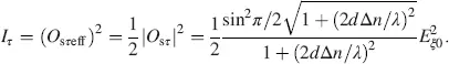
The reduced transmission  is plotted in Figure 4.3versus a = 2 d Δ n / λ . Zeros occur for
 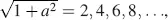 and hence for
 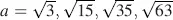 . In the first minimum we obtain, with
  from Equation (4.55), the optical retardation
(4.60) 
and the thickness d for a given λ = λ 0as
(4.61) 
The d value is larger by a factor  than the corresponding one for the Fréederickzs or the DAP cell in Equation (3.80). The thicker cell can be manufactured with a larger yield, as the risk of generating shorts by dust particles in the cell is reduced. Obviously, the effective retardation in a twisted cell is smaller than in an untwisted one, resulting in a larger thickness. A similar effect is already known from the HAN cell.
According to Equation (4.61), the blocking of light with λ 0= 550 nm requires with Δ n = 0 15 a thickness d = 3.1 μ when working at the first minimum.
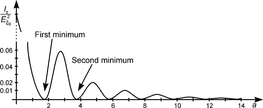
Figure 4.3The intensity of light passing through a non-addressed TN-LCD with twist angle β = π /2 with a = 2 d Δ n / λ according to Equation (4.59)
Extinction of the light in Figure 4.3occurs only for one wavelength λ . Neighbouring wavelengths can pass, which light up the black state with a bluish-yellowish tint. Hence, this normally black mode provides a poor black state. It will be enhanced by compensation foils introduced in Chapter 6.
In the addressed state with the maximum voltage around 6V all LC molecules have aligned for Δ ε > 0 in parallel to the electric field. The incoming linearly polarized light experiences no birefringence and arrives unchanged at the parallel analyser, which can be passed. The transmission T of light for this normally black cell is depicted versus the reduced voltage across the cell in Figure 2.13.
In the operation with crossed polarizers leading to the normally white mode, the analyser lies in the σ -direction in Figure 4.1. The pertinent Jones vector O sσfor the field-free state is given in Equation (4.57), from which the intensity Iσ passing the analyser follows as
(4.62) 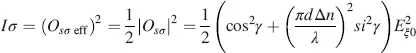
with γ in Equation (4.56). This leads to
(4.63) 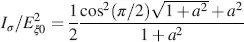
with a in Equation (4.55).
This reduced intensity is plotted versus a in Figure 4.4. The values are considerably larger than in the normally black mode in Figure 4.3. If the cell is fully addressed, the LC molecules orient themselves parallel to the field, and hence the incoming light, linearly polarized along the x -axis, reaches the crossed analyser unchanged, and is hence blocked independent of the wavelength. This generates an excellent black state if a field is applied. Therefore, the normally white cell is the preferred LCD.
The black state is independent of the thickness d . In the white state in Equation (4.63)and in Figure 4.4, the first maximum of the intensity lies in the vicinity of the first maximum of the cos term occurring at  , and hence
  , leading again with a in Equation (4.55)to
 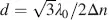 , as for the normally black mode. Further maxima occur around
 or
or  as for the minima in the normally black mode. The maxima are of equal height l/2.
Figure 4.4The intensity of light passing through a non-addressed normally white TN-LCD with twist angle β = π /2 and with a = 2 d Δ n / λ according to Equation (4.63)
4.2.2 The supertwisted nematic LC cell (STN-LCD)
Linear polarized light is fed into the STN cell (Scheffer and Nehring, 1998) again with α = 0 in Figure 4.1. The twist angle β at z = d is, however, β > π /2, with values typically between π and 3( π /2). With the twist angle β in Equation (4.49)and a in Equation (4.48), we rewrite γ in Equation (4.47)with p from Equation (4.49)as
(4.64) 
With γ in Equation (4.64), and β 0in Equation (4.50), Equation (4.52)governing the field-free state provides for the coordinates x ′ and y ′ with the angle ψ in Figure 4.1, and again, drawn in Figure 4.5
(4.65) 
leading to
(4.66) 
Интервал:
Закладка:
Похожие книги на «Liquid Crystal Displays»
Представляем Вашему вниманию похожие книги на «Liquid Crystal Displays» списком для выбора. Мы отобрали схожую по названию и смыслу литературу в надежде предоставить читателям больше вариантов отыскать новые, интересные, ещё непрочитанные произведения.


Обсуждение, отзывы о книге «Liquid Crystal Displays» и просто собственные мнения читателей. Оставьте ваши комментарии, напишите, что Вы думаете о произведении, его смысле или главных героях. Укажите что конкретно понравилось, а что нет, и почему Вы так считаете.