Ernst Lueder - Liquid Crystal Displays
Здесь есть возможность читать онлайн «Ernst Lueder - Liquid Crystal Displays» — ознакомительный отрывок электронной книги совершенно бесплатно, а после прочтения отрывка купить полную версию. В некоторых случаях можно слушать аудио, скачать через торрент в формате fb2 и присутствует краткое содержание. Жанр: unrecognised, на английском языке. Описание произведения, (предисловие) а так же отзывы посетителей доступны на портале библиотеки ЛибКат.
- Название:Liquid Crystal Displays
- Автор:
- Жанр:
- Год:неизвестен
- ISBN:нет данных
- Рейтинг книги:4 / 5. Голосов: 1
-
Избранное:Добавить в избранное
- Отзывы:
-
Ваша оценка:
Liquid Crystal Displays: краткое содержание, описание и аннотация
Предлагаем к чтению аннотацию, описание, краткое содержание или предисловие (зависит от того, что написал сам автор книги «Liquid Crystal Displays»). Если вы не нашли необходимую информацию о книге — напишите в комментариях, мы постараемся отыскать её.
THE NEW EDITION OF THE GOLD-STANDARD IN TEACHING AND REFERENCING THE FUNDAMENTALS OF LCD TECHNOLOGIES
Liquid Crystal Displays — читать онлайн ознакомительный отрывок
Ниже представлен текст книги, разбитый по страницам. Система сохранения места последней прочитанной страницы, позволяет с удобством читать онлайн бесплатно книгу «Liquid Crystal Displays», без необходимости каждый раз заново искать на чём Вы остановились. Поставьте закладку, и сможете в любой момент перейти на страницу, на которой закончили чтение.
Интервал:
Закладка:
14 Saito, S. and Yamamoto, H. (1978) Transient behaviors of field-induced reorientation in variously oriented nematic liquid crystals. Jap. J. ofAppl. Phys., 17(2).
15 Uchida, T. (1999) High performance reflective color LCDs. Proc. Eurodisplay 99, Berlin.
16 Vithana, H. K. M. and Faris, S. M. (1997) Polymer stabilized Pi-cells as switchable phase retarders. SID 1997 Digest.
17 Yang, Y. C. etal. (2009) Sub-millisecond liquid crystal mode utilizing electro-optic Kerr effect comprising polymer-stabilized isotropic liquid crystals. SID 09, p. 586.
18 Yeh, P. (1988) Optical Waves in Layered Media. John Wiley & Sons, Chichester.
19 Yeh, P. and Gu, C. (1999) Optics of Liquid Crystal Displays. John Wiley & Sons, Chichester.
4
Electro-optic Effects in Twisted Nematic Liquid Crystals
4.1 The Propagation of Polarized Light in Twisted Nematic Liquid Crystal Cells
The Twisted Nematic cell (TN cell) is the most widely commercially used LC cell. It was proposed by Schadt and Helfrich (1971), and is therefore also termed the Schadt–Helfrich cell. The theoretical investigation is based on Jones vectors. Solutions for the light exiting a TN cell were given by Yeh (1998), Yeh and Gu (1999), Grinberg and Jacobson (1976) and Rosenbluth et al . (1998). The derivation relies on rotating back the coordinate system to the original coordinates in twisted media and on the Chebychev identity of matrices (Bodewig, 1959). On the other hand, the derivation of the results presented here rotates the coordinates with the twist of the layers. The further calculation is based on Specht (2000).
The planar wave with wave vector  at the input of the cell propagates along the z -axis in Figure 4.1. We investigate the propagation through the cell without considering the light reflected at the LC molecules or absorbed in the cell. The incoming light is linearly polarized in the ξ -direction at an angle α to the x -axis with the electrical field Eξ 0giving the Jones vector
(4.1) 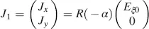
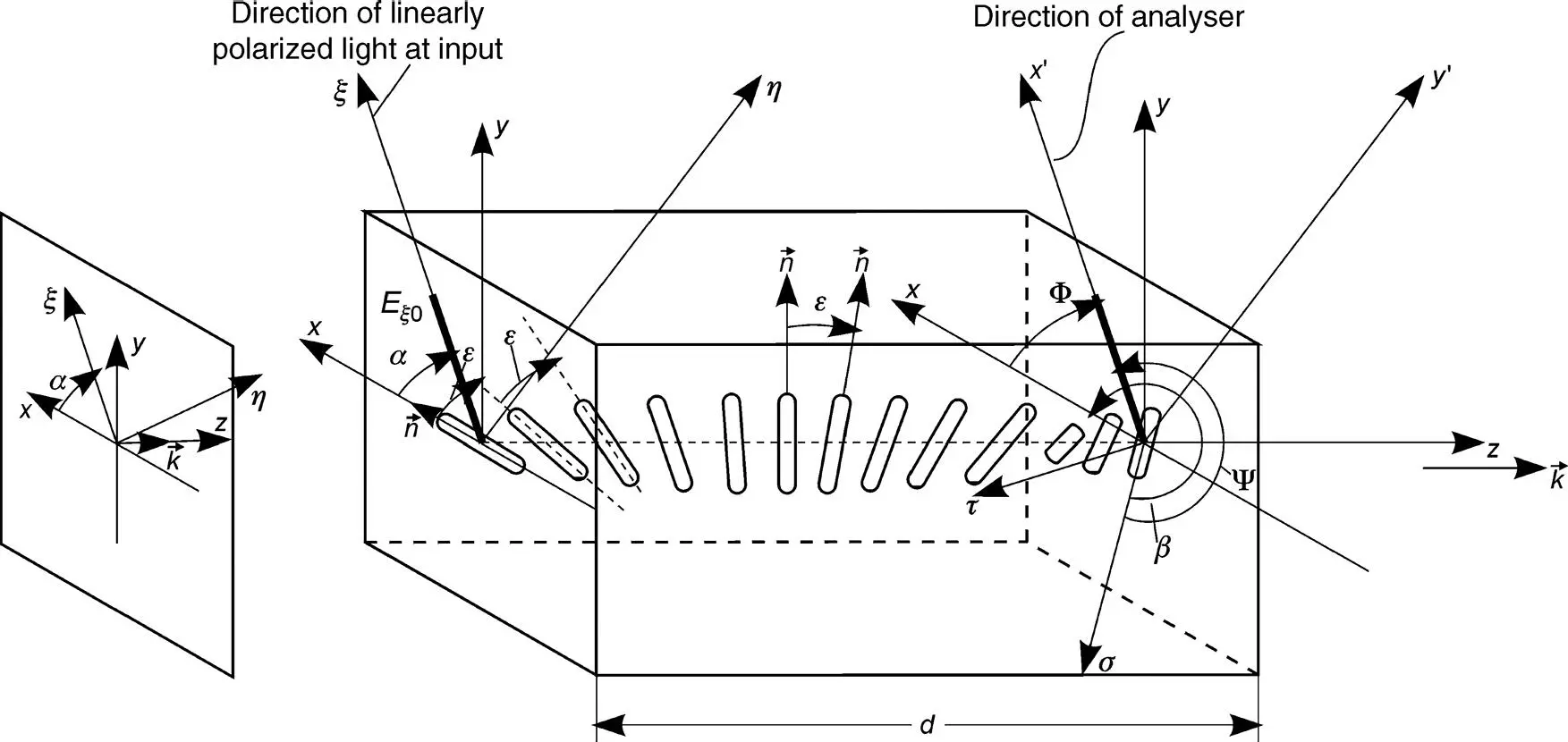
Figure 4.1The general twisted nematic LCD with twist angle β
in the x – y coordinates. The LC molecules in the x – y plane are all anchored in the rubbing grooves parallel to the x -direction. The directors of all molecules in the cell are parallel to the x – y plane and form a helix with the z -direction as the axis, and with the linear twist angle
(4.2) 
a pitch p given by
(4.3) 
and a twist angle
(4.4) 
at z = d . For calculations, the helix is cut into slices parallel to the x–y plane. In each slice, all molecules are assumed to be parallel. The slices are rotated from the previous slice by the angle ε . The angle ε corresponds to a thickness dε with

or
(4.5) 
for each slice. The twist angle at z = d is from Equation (4.4)with α 0in Equation (4.3)
(4.6) 
whereas the number of slices in the cell is with Equation (4.5)
(4.7) 
The Jones vector J 1at the input is translated into the vector O 1at the output of the first slice with thickness dε . Its component J 1xis parallel to the x -axis and the component J 1yis parallel to the y- axis, and hence (as already known from the Fréedericksz cell),without the need to rotate the input vector, we obtain
(4.8) 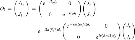
or
(4.9) 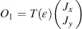
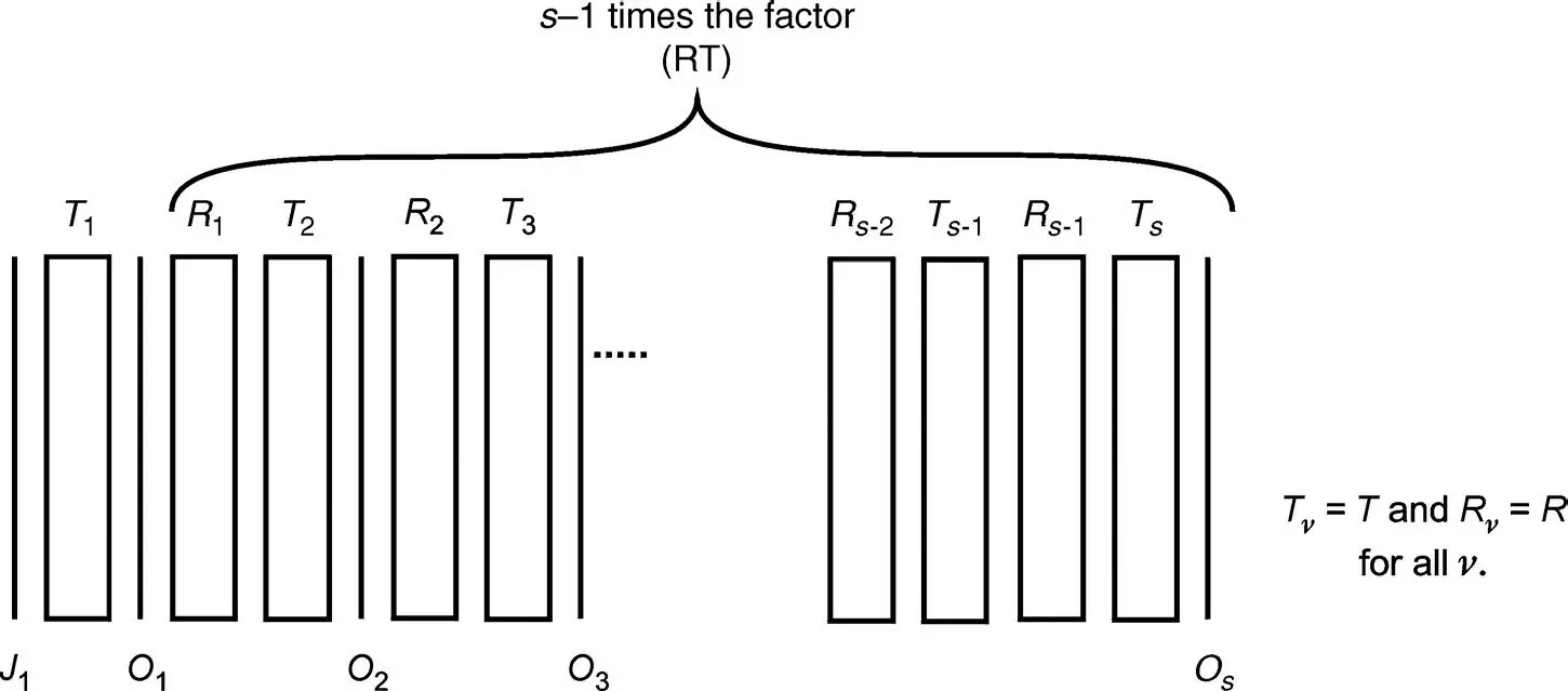
Figure 4.2The propagation of light from the Jones vector J 1at the input to the Jones vector O sat the output through the transmission matrices Tv and the rotation matrices Rv
with

where  and
and  in Equations (3.33)and (3.34)were used.
The further propagation of the light through the s − 1 remaining rotated slices is depicted in Figure 4.2with the rotation matrices
(4.10) 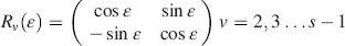
and the transmission matrices
(4.11) 
The Jones vector Os at the output at z = d measured in the coordinates σ and τ with the angle β to the x -axis in Figure 4.1is, with Equations (4.1)and (4.9)
(4.12) 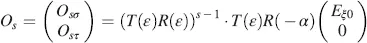
or with Equations (4.10), (4.11), dε in Equation (4.5), s in Equation (4.7)and
(4.13) 
(4.14) 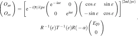
Интервал:
Закладка:
Похожие книги на «Liquid Crystal Displays»
Представляем Вашему вниманию похожие книги на «Liquid Crystal Displays» списком для выбора. Мы отобрали схожую по названию и смыслу литературу в надежде предоставить читателям больше вариантов отыскать новые, интересные, ещё непрочитанные произведения.


Обсуждение, отзывы о книге «Liquid Crystal Displays» и просто собственные мнения читателей. Оставьте ваши комментарии, напишите, что Вы думаете о произведении, его смысле или главных героях. Укажите что конкретно понравилось, а что нет, и почему Вы так считаете.