Ernst Lueder - Liquid Crystal Displays
Здесь есть возможность читать онлайн «Ernst Lueder - Liquid Crystal Displays» — ознакомительный отрывок электронной книги совершенно бесплатно, а после прочтения отрывка купить полную версию. В некоторых случаях можно слушать аудио, скачать через торрент в формате fb2 и присутствует краткое содержание. Жанр: unrecognised, на английском языке. Описание произведения, (предисловие) а так же отзывы посетителей доступны на портале библиотеки ЛибКат.
- Название:Liquid Crystal Displays
- Автор:
- Жанр:
- Год:неизвестен
- ISBN:нет данных
- Рейтинг книги:4 / 5. Голосов: 1
-
Избранное:Добавить в избранное
- Отзывы:
-
Ваша оценка:
Liquid Crystal Displays: краткое содержание, описание и аннотация
Предлагаем к чтению аннотацию, описание, краткое содержание или предисловие (зависит от того, что написал сам автор книги «Liquid Crystal Displays»). Если вы не нашли необходимую информацию о книге — напишите в комментариях, мы постараемся отыскать её.
THE NEW EDITION OF THE GOLD-STANDARD IN TEACHING AND REFERENCING THE FUNDAMENTALS OF LCD TECHNOLOGIES
Liquid Crystal Displays — читать онлайн ознакомительный отрывок
Ниже представлен текст книги, разбитый по страницам. Система сохранения места последней прочитанной страницы, позволяет с удобством читать онлайн бесплатно книгу «Liquid Crystal Displays», без необходимости каждый раз заново искать на чём Вы остановились. Поставьте закладку, и сможете в любой момент перейти на страницу, на которой закончили чтение.
Интервал:
Закладка:
(3.103) 
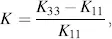
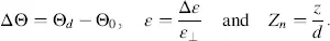
with


For Θ d= Θо = π /2 we obtain the rise time for the Fréedericksz cell as
(3.104) 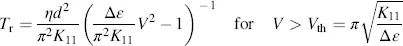
and for Θ d= Θ о= 0 the rise time of the DAP cell as
(3.105) 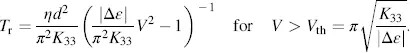
These two results have already been published in Labrunie and Robert (1973).
The threshold voltage in both cases can be detected from the denominators of Tr in the Equations (3.104)and (3.105)as points where T rbecomes infinite. Obviously, T rincreases with the viscosity η and the square of the thickness d independent of Θ dand Θ 0. Figure 3.24shows the normalized rise time T rn= T r/ ηd2 / π2K 11versus the normalized voltage 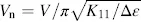 calculated from Equation (3.103)for a p -type nematic with Δ ε = 0.55 and K= 0.16 for various angles Θ dand Θ 0. The Fréedericksz cell (planar cell) with Θ d= Θ 0= 90° exhibits a larger rise time than all of the other cells, including the HAN cell with Θ 0= 0 and Θ d= π /2. The pronounced decrease of T mat
  , as shown in Equation (3.104), is also clearly visible in Figure 3.24(a). Figure 3.24(b)depicts the normalized rise time
 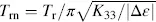 versus the normalized voltage
 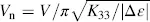 , again calculated from Equation (3.103), but this time for an n -type nematic LC with Δ ε = −0.12 and K = 0.43 for various angles Θ dand Θ 0. In this case, the rise time of the DAP cell with Θ d= Θ 0= 0 exceeds the rise time of all other cells. Thus, in both cases, the Fréedericksz cell and the DAP cell are slower than all of the other cells with different combinations of pretilt angles. The decrease of T mwith increasing V nagain takes place only for
  .
.
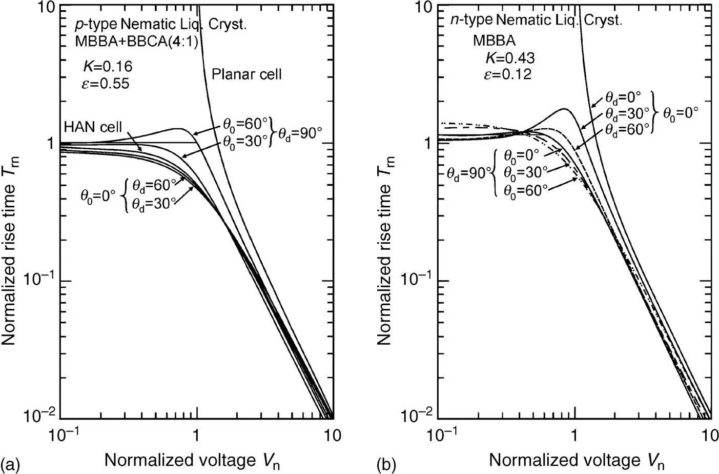
Figure 3.24 Normalized rise time T mversus normalized voltage V nwith various tilt angles θd and θ 0 . (a) For p -type and (b) n -type nematic LCs
Finally, Figures 3.25(a)and 3.25(b)depict T mversus V nwith K= (K 33− K ||)/ K ||as a parameter for a p -type and an n-type nematic LC. The Fréedericksz cell in Figure 3.25(a)and the DAP cell in Figure 3.25(b)are independent of K and slower than all the HAN cells with different values of K . The shorter rise time of the HAN cell over the other cells can phenomenologically be explained by the fact that half of the molecules are already rotated in the direction imposed by the field, horizontally for Δ ε < 0 and vertically for Δ ε > 0. The decay time Td is derived in Saito and Yamamoto (1978) as
(3.106) 
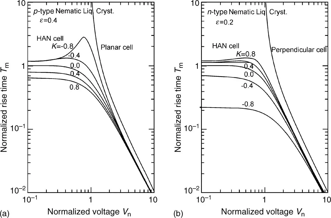
Figure 3.25 Normalized rise time T mversus normalized voltage V nwith the ratio K of elastic constants as parameter (a) for p -type and (b) n -type nematic LCs
which is independent of the applied voltage V and of Δ ε , and has the same factor outside the magnitude sign as T rin Equation (3.103). For Θ d= Θ 0= π/2 we obtain T dof the Fréedericksz cell as
(3.107) 
and for Θ d= Θ 0= 0 T dof the DAP cell as
(3.108) 
whereas the decay time for the HAN cell is obtained by putting Θ d= π/2 and Θ 0= 0, yielding
(3.109) 
A comparison between the HAN cell and the Fréedericksz cell which is valid for p -type nematic LCs reveals for the same cell-thickness
(3.110) 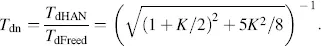
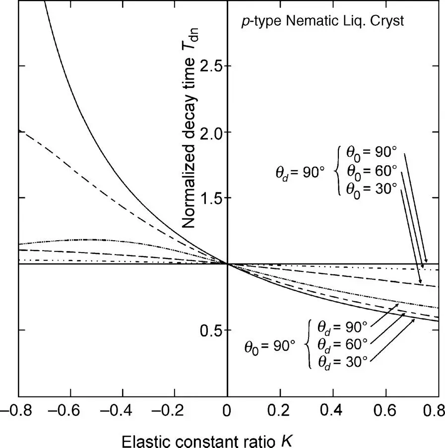
Figure 3.26 The ratio T dnin Equation (3.110)versus K for a p -type nematic LC
For K > 0 the decay time of the HAN cell is shorter, and for − 1 < K< 0 longer than that of the Freedericksz cell, whereas they are equal for K= 0 reached by K 11= K 33. Comparing the HAN cell to the DAP cell, which applies for n -type nematic LCs, yields for the same cell thickness
Читать дальшеИнтервал:
Закладка:
Похожие книги на «Liquid Crystal Displays»
Представляем Вашему вниманию похожие книги на «Liquid Crystal Displays» списком для выбора. Мы отобрали схожую по названию и смыслу литературу в надежде предоставить читателям больше вариантов отыскать новые, интересные, ещё непрочитанные произведения.


Обсуждение, отзывы о книге «Liquid Crystal Displays» и просто собственные мнения читателей. Оставьте ваши комментарии, напишите, что Вы думаете о произведении, его смысле или главных героях. Укажите что конкретно понравилось, а что нет, и почему Вы так считаете.