Ernst Lueder - Liquid Crystal Displays
Здесь есть возможность читать онлайн «Ernst Lueder - Liquid Crystal Displays» — ознакомительный отрывок электронной книги совершенно бесплатно, а после прочтения отрывка купить полную версию. В некоторых случаях можно слушать аудио, скачать через торрент в формате fb2 и присутствует краткое содержание. Жанр: unrecognised, на английском языке. Описание произведения, (предисловие) а так же отзывы посетителей доступны на портале библиотеки ЛибКат.
- Название:Liquid Crystal Displays
- Автор:
- Жанр:
- Год:неизвестен
- ISBN:нет данных
- Рейтинг книги:4 / 5. Голосов: 1
-
Избранное:Добавить в избранное
- Отзывы:
-
Ваша оценка:
Liquid Crystal Displays: краткое содержание, описание и аннотация
Предлагаем к чтению аннотацию, описание, краткое содержание или предисловие (зависит от того, что написал сам автор книги «Liquid Crystal Displays»). Если вы не нашли необходимую информацию о книге — напишите в комментариях, мы постараемся отыскать её.
THE NEW EDITION OF THE GOLD-STANDARD IN TEACHING AND REFERENCING THE FUNDAMENTALS OF LCD TECHNOLOGIES
Liquid Crystal Displays — читать онлайн ознакомительный отрывок
Ниже представлен текст книги, разбитый по страницам. Система сохранения места последней прочитанной страницы, позволяет с удобством читать онлайн бесплатно книгу «Liquid Crystal Displays», без необходимости каждый раз заново искать на чём Вы остановились. Поставьте закладку, и сможете в любой момент перейти на страницу, на которой закончили чтение.
Интервал:
Закладка:
Luminance is the correct term for ‘brightness’. The physical meaning and dimensions of luminance and other display-related units are explained in Appendix 2.
The blocking of light in the analyser as described by Equation (2.15)is only valid for one wavelength for which, as a rule, yellow light with λ = 505 nm is chosen. As other wavelengths can still pass the analyser, the black state is not perfect. As a rule, it has a bluish tint. The imperfect black state can be improved by compensation foils, as discussed later.
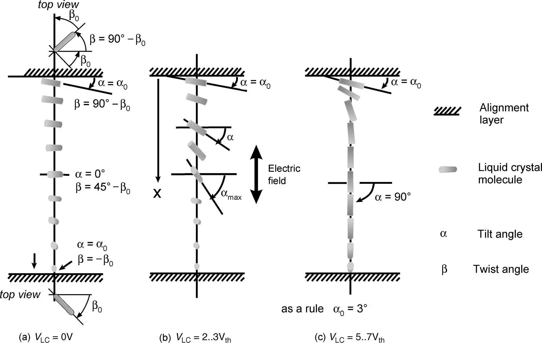
Figure 2.12 Change in the position of the LC molecules with increasing voltage
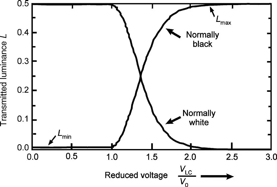
Figure 2.13 Transmitted luminance versus the reduced voltage V LCacross the LC cell for the normally white and normally black modes
(2.16) 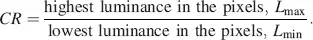
The measurement should be performed without the interference of reflected ambient light, i. e. in darkness. If the black state in the denominator of Equation (2.16)is increased by the imperfect blocking of the light, contrast falls in any case. This is the case in the normally black state, whereas the normally white state described above yields an excellent contrast due to a much lower value of the denominator in Equation (2.16).
Grey shades of a pixel are controlled by the voltage V LCin Figure 2.13, which modulates the luminance from a full but imperfect black up to a full white. Luminance differs when the display is viewed under angles different from perpendicular to the glass plates. Contrast decreases the more oblique the angles become.
The TFT addressing circuit will be placed on the glass next to the backlight in Figure 2.10. In a colour display, the glass plate facing the viewer carries the pixellized colour filter, shown in Figure 2.14. The pixels for red, green and blue are covered with a compound which absorbs all wavelengths originating from the white backlight besides red, green and blue, respectively. The saturation of the colours is individually controlled for each pixel by the voltage V LCin the same way as for grey shades.
The geometrical arrangement of the colour pixels in triangles in Figure 2.14(a)and along diagonals in Figure 2.14(c)are recommended for moving TV pictures, whereas the colour stripes in Figure 2.14(b)are preferred for computer displays often presenting rectangular graphs.
The cross-section of a colour filter in Figure 2.15contains the colour materials for R, G and B, an absorptive layer with a low reflection in between the pixels, a so-called black matrix, an overcoat layer and, in the case of TFT addressing, an unpixellized ITO electrode over the entire display area. For other addressing schemes, the ITO layer is no longer unstructured. The ITO electrode on the TFT-carrying plate is pixellized. The black matrix prevents light between the pixels, which is neither controlled by the voltage V LCat the ITO electrodes nor exhibits the desired colour, from seeping through the cell. This light would lighten up the black state, and would thus degrade contrast and the saturation of colour. A suitable material for a black matrix is an organic material with carbon particles exhibiting a reflectivity of only 4 percent, whereas the previously used Cr-oxide has a reflectivity of 40 percent. The overcoat layer (e.g. out of a methacrylate resin solution) equalizes the different heights of the colour pixels and protects them.
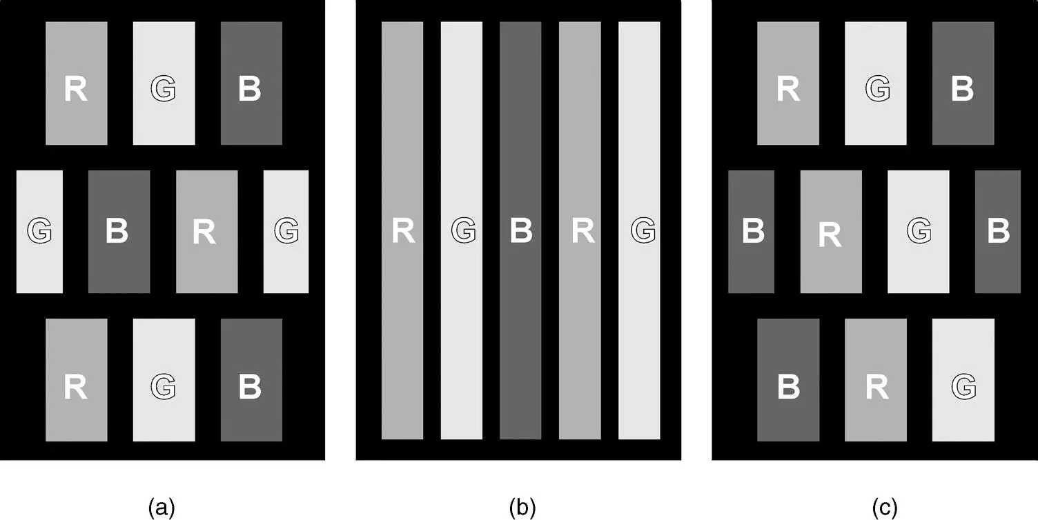
Figure 2.14 The geometrical arrangement of colour pixels for red R, green G, and blue B (a) in triangles, (b) in stripes and (c) in diagonal form
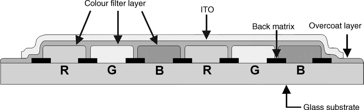
Figure 2.15 Cross-section of a colour filter for TFT addressed LCDs
2.2.2 The addressing of LCDs by TFTs
So far we know that we have to control the grey shade individually in each pixel by applying the appropriate pixel voltage V LC, but by only using the external contact pads in Figure 2.9. The TFT-addressed LCD, usually called an Active Matrix LCD (AMLCD), solves this task as depicted in Figure 2.16. It shows two pixels of a row of pixels, with the row- and column- conductors and ground represented by the unstructured ITO electrode on the colour plate in Figure 2.15. The TFTs are n -channel Field Effect Transistors (FETs) fabricated with thin film technology. They operate as switches in the pixels. All TFTs in a row are rendered conductive by a positive gate impulse V g. TFTs in other rows are blocked by grounding the rows. The video information is fed in through the columns and the conducting TFTs into all the pixels of a row simultaneously. More specifically, the video voltage V dcorresponding to a desired grey shade charges the LC-capacitor C LCand an additional thin-film storage capacitor C sup to the voltage V d. This constitutes an amplitude modulation. The operation addresses one line at a time, as opposed to one pixel at a time, of the e -beam in CRTs. During the charging time, the storage capacitor connected to the succeeding line n + 1 is grounded, and hence connected in parallel to C LC. As this is no more true during other phases of the operation, degradations of the addressing waveform are introduced, as discussed later.
The pixel switches have to charge N rows in the frame time T fin which a picture is written. Hence, the row-address time is
(2.17) 
The waveform of the pixel-voltage V LCis depicted in Figure 2.17. In the time T r, the storage capacitors are charged with the time constant
(2.18) 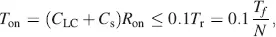
where R onis the on-resistance of the TFT. The inequality guarantees that at the end of T r, the voltage V LCis only 1 percent below the desired voltage V din Figure 2.16. The TFTs need to be fast enough to make sure that even if their properties fluctuate, as indicated by dashed lines in Figure 2.17, they still charge the capacitors to the voltage V d. After the time Tr, the transistor is blocked, but still has a finite off-resistance R off. After T fthe row is addressed again and the new picture information is fed in. During this time, the discharge of the capacitors should be small to provide a luminance as constant as possible. This yields an almost flicker-free picture, again as opposed to the CRT, where in the absence of storage the luminance of the phosphor decays after having shortly been hit by the e-beam. The constraint for the time constant T offof the discharge is
Читать дальшеИнтервал:
Закладка:
Похожие книги на «Liquid Crystal Displays»
Представляем Вашему вниманию похожие книги на «Liquid Crystal Displays» списком для выбора. Мы отобрали схожую по названию и смыслу литературу в надежде предоставить читателям больше вариантов отыскать новые, интересные, ещё непрочитанные произведения.


Обсуждение, отзывы о книге «Liquid Crystal Displays» и просто собственные мнения читателей. Оставьте ваши комментарии, напишите, что Вы думаете о произведении, его смысле или главных героях. Укажите что конкретно понравилось, а что нет, и почему Вы так считаете.