Ernst Lueder - Liquid Crystal Displays
Здесь есть возможность читать онлайн «Ernst Lueder - Liquid Crystal Displays» — ознакомительный отрывок электронной книги совершенно бесплатно, а после прочтения отрывка купить полную версию. В некоторых случаях можно слушать аудио, скачать через торрент в формате fb2 и присутствует краткое содержание. Жанр: unrecognised, на английском языке. Описание произведения, (предисловие) а так же отзывы посетителей доступны на портале библиотеки ЛибКат.
- Название:Liquid Crystal Displays
- Автор:
- Жанр:
- Год:неизвестен
- ISBN:нет данных
- Рейтинг книги:4 / 5. Голосов: 1
-
Избранное:Добавить в избранное
- Отзывы:
-
Ваша оценка:
Liquid Crystal Displays: краткое содержание, описание и аннотация
Предлагаем к чтению аннотацию, описание, краткое содержание или предисловие (зависит от того, что написал сам автор книги «Liquid Crystal Displays»). Если вы не нашли необходимую информацию о книге — напишите в комментариях, мы постараемся отыскать её.
THE NEW EDITION OF THE GOLD-STANDARD IN TEACHING AND REFERENCING THE FUNDAMENTALS OF LCD TECHNOLOGIES
Liquid Crystal Displays — читать онлайн ознакомительный отрывок
Ниже представлен текст книги, разбитый по страницам. Система сохранения места последней прочитанной страницы, позволяет с удобством читать онлайн бесплатно книгу «Liquid Crystal Displays», без необходимости каждый раз заново искать на чём Вы остановились. Поставьте закладку, и сможете в любой момент перейти на страницу, на которой закончили чтение.
Интервал:
Закладка:
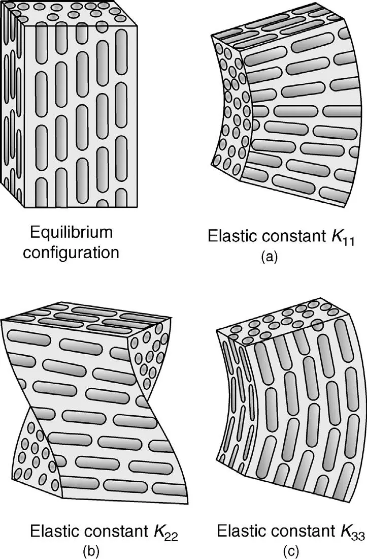
Figure 2.7 Equilibrium configuration; the elastic deformations splay (a), twist (b) and bend (c)
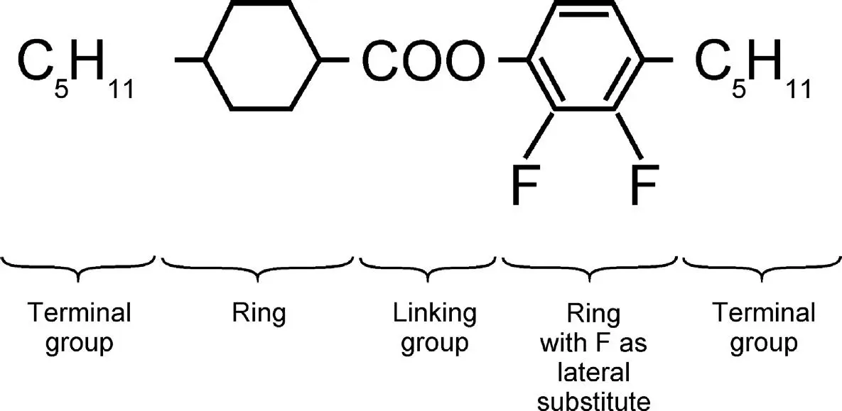
Figure 2.8 The basic structure of a calamitic LC molecule
2.2 The Operation of a Twisted Nematic LCD
The liquid crystals used are calamitic and thermotropic in the nematic phase. The operation of this most widely applied LCD will be phenomenologically described in order to give an overview over the entire flat panel display system, including the addressing scheme (Demus et al., 1998a; Kaneko, 1987; Lueder, 1998a). This alleviates the more analytical and detailed treatments that follow.
2.2.1 The electro-optical effects in transmissive twisted nematic LC cells
Figure 2.9depicts the top view of a display panel with the conducting rows and columns terminating in the contact pads. The rectangular pixels can only be electrically addressed from those contact pads.
A colour VGA display, as used in laptops, has 480 rows and 3 × 320 columns forming triple dots for the three colours red, green and blue. An NTSC TV display has 484 rows and 3 × 450 columns corresponding to 653 400 pixels, whereas an HDTV display has 1080 × 3 × 1920 = 7320 800 pixels. For more standardized formats, see the table in Appendix 1.
Table 2.2 Properties of nematic LC materials with a wide temperature range
| MLC-1380000 | MLC-13800100 | MLC-1390000 | MLC-13900100 | |
|---|---|---|---|---|
| Transition temp, smectic-nematic | < −40°C | < −40°C | < −40°C | < −40°C |
| Clearing pt T c | 110 °C | 111°C | 110.5 °C | |
| Rotational viscosity, 20 °C | 228 mPas | 151 mPas | 235 mPas | 167 mPas |
| Δ ε 1 kHz 20 °C | + 8.9 | + 5.0 | + 8.3 | ++ 5.2 |
| n 0 = n┴ | 1.4720 | 1.4832 | 1.4816 | 1.4906 |
| ne= n || | 1.5622 | 1.5735 | 1.5888 | 1.5987 |
| Δ n | + 0.0902 | +0.0903 | 0.1073 | + 0.1081 |
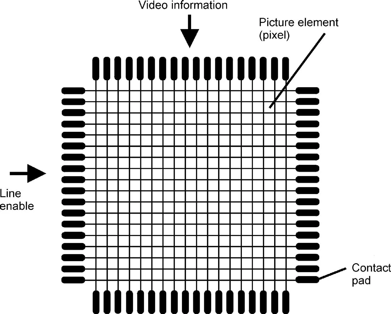
Figure 2.9 Top view of the rows, columns, pixels and contact pads of a display panel
Figure 2.10shows a pixel of a transmissive twisted nematic LC cell with no voltage applied. The white backlight/passes the polarizer a. The light leaves it linearly polarized in the direction of the lines in the polarizer, and passes the glass substrate b , the transparent electrode c out of Indium-Tin-Oxide (ITO) and the transparent orientation layer g . This layer, made of an organic material such as polyimide, 100 nm thick, is rubbed to generate grooves in the direction of the plane of the polarized light. In these grooves the rod-like LC molecules are all anchored in parallel, but, as shown in Figure 2.11, with a pretilt angle a 0to the surface of the orientation layer. The sequence of layers is the same on the second glass plate. A typical thickness of the cell in Figure 2.10is d= 3.5 μ to 4.5 μ. The grooves on the second plate are perpendicular to those on the first plate. This forces the liquid crystal molecules to twist on a helix by β = 90° from one plate to the other without the addition of chiral compounds. All twist angles are called β.
Due to the birefringence, the components of the electric field vector of the light in parallel and perpendicular to the directors travel with different speeds, which depend upon the wavelength. They superimpose along their path between the two glass plates first to elliptically polarized light, in the distance d /2 from the input to circularly polarized light, then again to an elliptic polarization, and if
(2.15) 
they reach the analyser again linearly polarized, but with the polarization plane rotated by 90°. If the analyser is crossed with the polarizer, the light can pass the analyser. The pixel appears white. This operation is termed the normally white mode. If the analyser is rotated by 90°, a parallel analyser, the light is blocked in the analyser. The pixel is black. This is called the normally black mode. A useful visualization of what happens to the light while travelling through the cell is as follows: the planes of the various polarizations follow the twist of the helix. This is, however, only true if Equation (2.15)holds. The explanation is also only true for light travelling and viewed perpendicular to the plane of the substrate. If viewed under a different angle, light perceived by the eye has travelled in a different path with different angles to the director and a different cell thickness d .
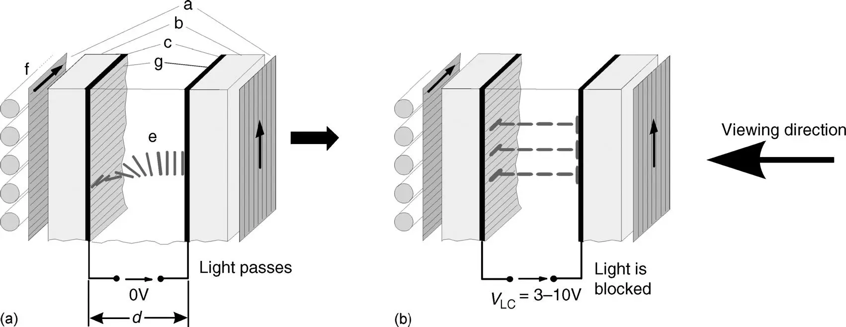
Figure 2.10 The structure of a TN-LCD (a) while light is passing, and (b) while light is blocked, a: polarizer; b: glass substrate; c; transparent electrode; g; orientation layer; e: liquid crystal; f: illumination
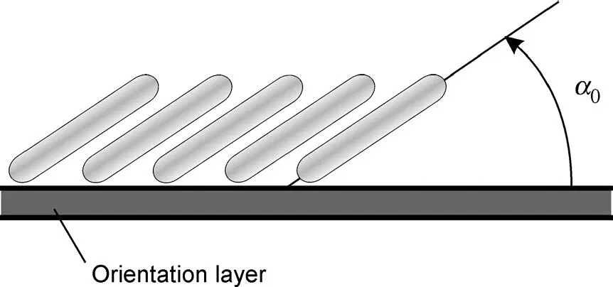
Figure 2.11 LC molecules with pretilt angle a 0on top of the orientation layer
If a voltage V LCof the order of 2 V is applied across the cell, as shown in Figure 2.10(b), using the two transparent ITO-electrodes 100 nm thick, the resulting electric field attempts to align the molecules for Δ ε > 0 parallel to the field. This holds independent of the sign of the vector of the electrical field, as already pointed out in Section 2.1.2. Hence, the following effects are not dependent on the polarity of V LC. Due to the anchoring forces, a thin LC layer on top of the orientation layers maintains its position almost parallel to the surfaces. A threshold voltage V this needed to overcome intermolecular forces before the twisted molecules start to rotate. A uniform start over the plane of the panel is favoured by a pretilt angle around 3°, which seems to avoid strong differences in the anchoring forces. Only at a saturation voltage V maxseveral times V thwith a value around 10 V have all molecules besides those on top of the orientation layers aligned parallel to the electric field, as depicted in Figure 2.10(b). In this state the vector of the electrical field of the incoming light oscillates perpendicular to the directors, and encounters only the refractive index n┴ . Hence, no birefringence takes place and the wave reaches the crossed analyser in the same linearly polarized form as at the input. The analyser blocks the light and the pixel appears black. This is an excellent black state as it is independent of the wavelength, resulting in a blocking of the light. This black state is gradually reached from the field-free initial state by increasing the voltage V LCfrom OV over an intermediate voltage up to V max, which is also gradually rotating the molecules in Figure 2.12from the initial twisted state with directors parallel to the surfaces ( Figure 2.10(a)) over an intermediate state with the director already tilted down with tilt angle a ( Figure 2.12(b)) to the final state with directors parallel (a = 90°) to the electric field. The transmitted luminance, also termed transmittance, of the light is shown in Figure 2.13for the normally white mode discussed so far. In the normally black mode, the analyser is parallel to the polarizer and allows the light to pass at the voltage V th≤ V LC≤ V max. For this mode the transmitted luminance is also depicted in Figure 2.13. Only in this mode is the threshold voltage V thvisible, as in the normally white mode a small change in luminance at a high value of the luminance cannot be perceived by the eye.
Читать дальшеИнтервал:
Закладка:
Похожие книги на «Liquid Crystal Displays»
Представляем Вашему вниманию похожие книги на «Liquid Crystal Displays» списком для выбора. Мы отобрали схожую по названию и смыслу литературу в надежде предоставить читателям больше вариантов отыскать новые, интересные, ещё непрочитанные произведения.


Обсуждение, отзывы о книге «Liquid Crystal Displays» и просто собственные мнения читателей. Оставьте ваши комментарии, напишите, что Вы думаете о произведении, его смысле или главных героях. Укажите что конкретно понравилось, а что нет, и почему Вы так считаете.