Magnetic Resonance Microscopy
Здесь есть возможность читать онлайн «Magnetic Resonance Microscopy» — ознакомительный отрывок электронной книги совершенно бесплатно, а после прочтения отрывка купить полную версию. В некоторых случаях можно слушать аудио, скачать через торрент в формате fb2 и присутствует краткое содержание. Жанр: unrecognised, на английском языке. Описание произведения, (предисловие) а так же отзывы посетителей доступны на портале библиотеки ЛибКат.
- Название:Magnetic Resonance Microscopy
- Автор:
- Жанр:
- Год:неизвестен
- ISBN:нет данных
- Рейтинг книги:4 / 5. Голосов: 1
-
Избранное:Добавить в избранное
- Отзывы:
-
Ваша оценка:
Magnetic Resonance Microscopy: краткое содержание, описание и аннотация
Предлагаем к чтению аннотацию, описание, краткое содержание или предисловие (зависит от того, что написал сам автор книги «Magnetic Resonance Microscopy»). Если вы не нашли необходимую информацию о книге — напишите в комментариях, мы постараемся отыскать её.
Explore the interdisciplinary applications of magnetic resonance microscopy in this one-of-a-kind resource Magnetic Resonance Microscopy: Instrumentation and Applications in Engineering, Life Science and Energy Research,
Magnetic Resonance Microscopy: Instrumentation and Applications in Engineering, Life Science and Energy Research
Magnetic Resonance Microscopy: Instrumentation and Applications in Engineering, Life Science and Energy Research
Magnetic Resonance Microscopy — читать онлайн ознакомительный отрывок
Ниже представлен текст книги, разбитый по страницам. Система сохранения места последней прочитанной страницы, позволяет с удобством читать онлайн бесплатно книгу «Magnetic Resonance Microscopy», без необходимости каждый раз заново искать на чём Вы остановились. Поставьте закладку, и сможете в любой момент перейти на страницу, на которой закончили чтение.
Интервал:
Закладка:
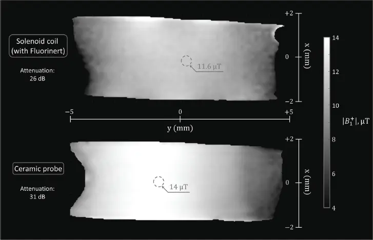
Figure 2.14 Measured transmit field pattern in a homogeneous liquid phantom for the reference optimal solenoid probe with Fluorinert (top) and for the designed ceramic (bottom), at 17.2 T. Data from [30].
The experimental SNR, measured in a tissue-mimicking liquid phantom, was also investigated for both probes in Figure 2.15 (left panel). With the same effective flip angle, the SNR was 2.2 times higher with the ceramic probe than with the solenoid immersed in Fluorinert. This has to be compared to the theoretical prediction: from Figure 2.7, for the designed ceramic probe (indicated as “proposed ceramics”), the semi-analytical method presented in Section 2.3 predicts an SNR gain of 2.5.
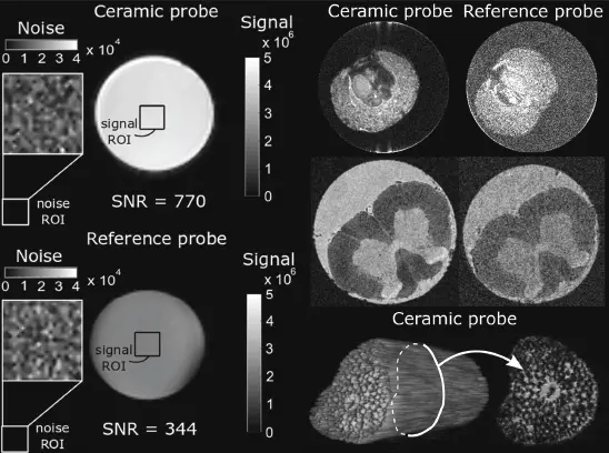
Figure 2.15 Experimental comparison of the designed ceramic probe and the reference optimal solenoid at 17 T. (Left) signal and noise maps measured in a homogeneous tissue-mimicking liquid phantom. (Right) microscopy images obtained with both probes; (first line) Ilex aquifolium fruit; (second line) chemically fixed rat spinal cord; (third line) 3D rendering and image slice of a plant petiole (obtained with the ceramic probe). With permission from [30].
Better performance of the ceramic probe can be observed in Figure 2.15 (right panel): microscopy images obtained with this probe demonstrate improved quality compared with those obtained using the reference probe, since more structural details can be distinguished.
2.4.3 Dual Ceramic Coils
Since ceramic probes are based on dielectric resonators, it is possible to exploit the coupling phenomenon between such objects positioned close to each other. Figure 2.16 depicts the coupling of the TE 01δmodes of two ring resonators each holding a sample, but the principle is the same for empty rings or disks. When the resonators are placed one above the other, the electromagnetic coupling of the individual modes (at the same frequency f 0) gives rise to two coupled modes: a lower-frequency mode denoted (++), with a field distribution such that the magnetic field between the resonators is enhanced; and a higher-frequency mode (+−) such that the magnetic field in between is decreased. In [32] the (++) mode of two coupled disks is exploited to image a sample held between the disks. In [33] two samples are imaged simultaneously by using the (++) mode of two ring resonators, each of them holding a sample. The corresponding magnetic field distribution is depicted in Figure 2.16 (right field maps, second line).
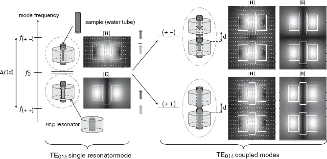
Figure 2.16 Coupling model of the first TE modes of two ring resonators. From [33].
Due to coupling, for the same input power, the SNR in each sample of the coupled ceramic probe is degraded by a factor of  compared with the single ceramic probe performance. However, in this study exploiting a prototype that had already overcome the reference solenoid probe by a factor of more than two, the coupled ceramic probe still provided a better SNR than the reference, with an SNR improvement of approximately 1.4, according to the theoretical modeling of the electromagnetic coupling and to numerical simulations. Experimental results from this work are shown in Figure 2.17, which displays plant petiole images obtained with the reference probe and the developed coupled ceramic probe. In the latter, two different samples are imaged, one in each dielectric resonator (DR). For sample 1, imaged with the solenoid and one of the coupled DRs, the maximum achieved SNR gain (dual ceramic probe over reference solenoid) is 1.2 (Figure 2.17c). Coupling these two resonators helps reduce the total acquisition time, since two samples can be imaged simultaneously.
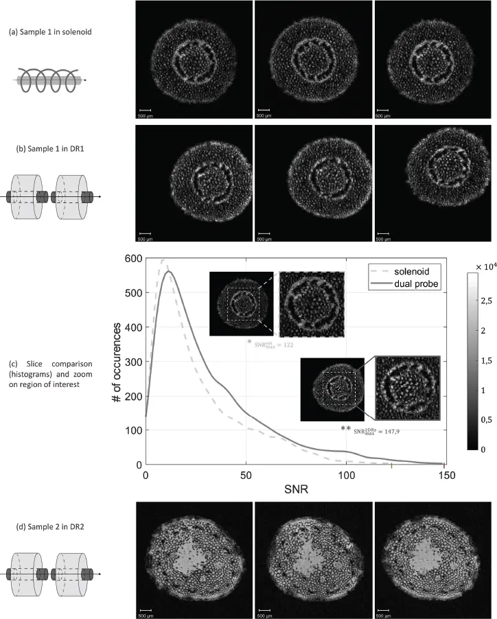
Figure 2.17 MR images of plant petioles using a solenoid coil and a ceramic probe exploiting the coupling of two dielectric ring resonators. In the latter, petioles from two different plants are imaged: sample 1 in (b) and sample 2 in (d), during the same acquisition time slot. Images of sample 1 are also acquired with the solenoid coil for comparison (a). A quantitative comparison of the two coils performance is provided in (c) with the signal-to-noise ratio (SNR) distribution of given regions of interest in sample 1. From [33] .
2.5 Conclusion and Future Prospects
While used for years in the field of microwave engineering, ceramic probes dedicated to MRI have only recently been developed for other various applications, from clinical imaging to microscopy. The principle is to excite one specific eigenmode of a high-permittivity resonator like a disk or ring, and to exploit the stimulated mode magnetic field as a transmit and/or receive field for MRI. The particularity of the eigenmodes used is the spatial coincidence of the maximum magnetic field with low electric field levels as well as the purely magnetically induced (nonconservative) nature of the electric field in the sample. Positioning the sample in this specific region therefore limits the losses due to the electric field interaction with the conductive biological materials, while keeping B 1values sufficiently high to perform imaging. The recent development of low-loss, high-permittivity ceramic materials has had a significant impact on the performance of dielectric probes, limiting the intrinsic losses.
Most probes proposed for MRM exploit the first TE mode of cylindrical high-permittivity resonators. Future work on developing probes exploiting the first hybrid mode would be beneficial to widen the possibilities of using ceramic probes. Another point of interest would be to develop arrays of ceramic probes to significantly reduce the acquisition time, which is a critical experimental parameter when performing MRI.
References
1 1Kajfez, D.and Guillon, P. (1998). Dielectric Resonators, 2e. Atlanta, GA: Noble Publishing Corporation.
2 2 Leung, K.W., Lim, E.H., and Fang, X.S. (2012). Dielectric resonator antennas: From the basic to the aesthetic. Proceedings of the IEEE 100 (7): 2181–2193.
3 3 Long, S.A., McAllister, M.W., and Shen, L.C. (1983). The resonant cylindrical dielectric cavity antenna. IEEE Transactions on Antennas and Propagation 31 (3): 406–412.
4 4Fiedziuszko, S.J. (1982). Dual-mode dielectric resonator loaded cavity filters. IEEE Transactions on Microwave Theory and Techniques 30 (9): 1311–1316.
5 5 Liang, X.P.and Zaki, K.A. (1993). Modeling of cylindrical dielectric resonators in rectangular waveguides and cavities. IEEE Transactions on Microwave Theory and Techniques 41 (12): 2174–2181.
6 6 Chen, S.W. (1991). Dielectric ring resonators loaded waveguide and on substrate. IEEE Transactions on Microwave Theory and Techniques 39 (12): 2069–2076.
7 7Webb, A.G. (2011). Dielectric materials in magnetic resonance. Concepts in Magnetic Resonance Part A 38 (4): 148–184.
8 8Golovina, I., Geifman, I., and Belous, A. (2008). New ceramic EPR resonators with high dielectric permittivity. Journal of Magnetic Resonance 195 (1): 52–59.
Читать дальшеИнтервал:
Закладка:
Похожие книги на «Magnetic Resonance Microscopy»
Представляем Вашему вниманию похожие книги на «Magnetic Resonance Microscopy» списком для выбора. Мы отобрали схожую по названию и смыслу литературу в надежде предоставить читателям больше вариантов отыскать новые, интересные, ещё непрочитанные произведения.


Обсуждение, отзывы о книге «Magnetic Resonance Microscopy» и просто собственные мнения читателей. Оставьте ваши комментарии, напишите, что Вы думаете о произведении, его смысле или главных героях. Укажите что конкретно понравилось, а что нет, и почему Вы так считаете.