Gennady Gromov - Thermoelectric Microgenerators. Optimization for energy harvesting
Здесь есть возможность читать онлайн «Gennady Gromov - Thermoelectric Microgenerators. Optimization for energy harvesting» — ознакомительный отрывок электронной книги совершенно бесплатно, а после прочтения отрывка купить полную версию. В некоторых случаях можно слушать аудио, скачать через торрент в формате fb2 и присутствует краткое содержание. ISBN: , Жанр: Физика, Прочая научная литература, на английском языке. Описание произведения, (предисловие) а так же отзывы посетителей доступны на портале библиотеки ЛибКат.
- Название:Thermoelectric Microgenerators. Optimization for energy harvesting
- Автор:
- Жанр:
- Год:неизвестен
- ISBN:978-5-4493-4334-5
- Рейтинг книги:3 / 5. Голосов: 1
-
Избранное:Добавить в избранное
- Отзывы:
-
Ваша оценка:
Thermoelectric Microgenerators. Optimization for energy harvesting: краткое содержание, описание и аннотация
Предлагаем к чтению аннотацию, описание, краткое содержание или предисловие (зависит от того, что написал сам автор книги «Thermoelectric Microgenerators. Optimization for energy harvesting»). Если вы не нашли необходимую информацию о книге — напишите в комментариях, мы постараемся отыскать её.
The structure of this book contains detailed explanations addressed to a wide range of readers, which for the most part are not specialists in the field of Thermoelectricity, the basic ideas, important aspects of the practical application of thermoelectric microgenerators in the in energy harvesting. I will be glad, if this book will serve as a reference tool in developing appropriate solutions.
Thermoelectric Microgenerators. Optimization for energy harvesting — читать онлайн ознакомительный отрывок
Ниже представлен текст книги, разбитый по страницам. Система сохранения места последней прочитанной страницы, позволяет с удобством читать онлайн бесплатно книгу «Thermoelectric Microgenerators. Optimization for energy harvesting», без необходимости каждый раз заново искать на чём Вы остановились. Поставьте закладку, и сможете в любой момент перейти на страницу, на которой закончили чтение.
Интервал:
Закладка:
Value of thermoEMF E and corerspoindingly output voltage U of generators are variable; depend on the value of temperature drop ∆ T . It is not so convenient for consumers of such non-stable power supply – to electronic devices.
Always it is necessary to use electronic DC-DC converter to transform the generator variable voltage to the standard supply voltage of electronic devices.
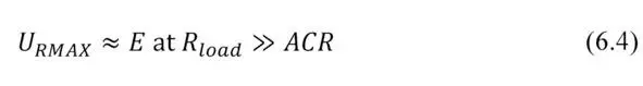
The DC-DC converters have restrictions on the minimum input voltage which they can transform. It needs to be taken into account. And thermoelectric generators selected for practical applications must be capable to give working voltage not below the minimum threshold of the applied DC-DC converter. In more detail about the choice of a DC-DC converters see Chapter 10.
Zones of applicability of modern DC-DC converters with the minimum input voltage are given in Fig. 6.1. It is, for instance, 20 mV (Linear Technology) [3], 80 mV and 250 mV (Texas Instruments) [4].
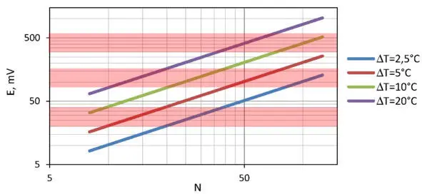
Figure. 6.1 ThermoEMF E depending on the number of pellet pairs N under various temperature differences Δ T.
Besides, low input voltage of the DC-DC converter requires to pay additional “cost”. It is the converter efficiency. The input voltage is lower – the efficiency of transformation of the DC-DC electronic scheme is lower.
In this regard it is more preferable to use generators giving the bigger thermoEMF, i.e. generators with a large number of thermoelements (see Fig. 6.1). Besides, practical tasks sometimes force to leave absolutely optimal solutions for generator. I.e. to use electric loads with a resistance bigger, than ACR , to increase the output voltage of the generator, though by reduction of generator’s efficiency.
It means to consider efficiencies of thermoelectric generator and DC-DC electrical circuit in a combination to obtain maximal output value (see Chapter 10).
Form-factor of thermoelements
The form-factor f of thermoelements of the generator module determines its total electric resistance.
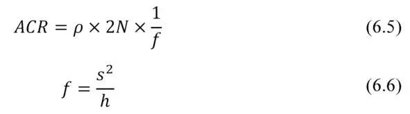
where f – form-factor of a thermoelement.
Here we neglect the additional resistance of the generator module construction (conductors, places of soldering of thermoelements, resistance of barrier layers). In most cases it is valid, as this additional resistance is insignificant usually in comparison of the sum of resistance of thermoelements (6.5).
Then
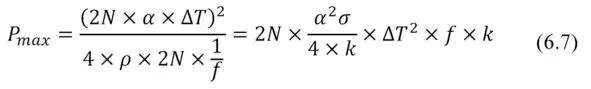
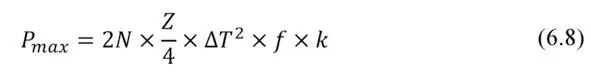
The formula for maximum power P max through the generator number of thermoelements N and their form-factor f has a finite shape
Thermal resistance
Thermal resistance Ȓ TEG of thermoelectric generator determines its overall performance.

Formula (6.8) can be converted to a dependence of maximum power P max vs thermal resistance Ȓ TEG of generator.
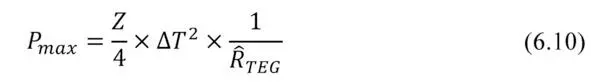
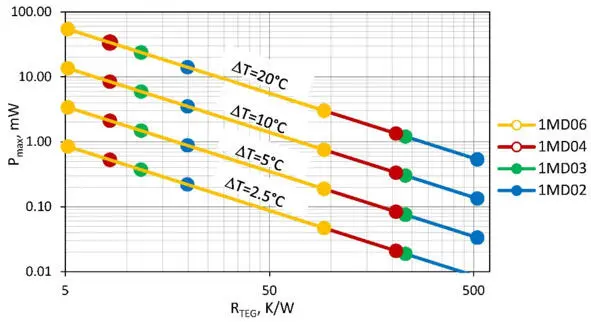
Figure. 6.2 Power P max of generators of different series (developed by TEC Microsystems) vs their thermal resistance Ȓ TEG at different temperature differences Δ T: Points mark the boundaries of the applicability of these series (1MD02, 1MD03, 1MD04 and 1MD06).
This formula (6.10) and the provided graph (Fig. 6.2) are important for understanding of features of practical applications of generator modules and the choice of optimal solutions.
The power provided by the generator depends on its Figure-of-Merit Z , thermal resistance Ȓ TEG and temperature difference ∆ T .
– Figure-of-Merit Z is defined by properties of the thermoelectric material used in the generator module and a design of the module. For different designs of generators average Figure-of-Merit Z – it a little changeable size is at the level of 2.8…3.0⨯10 —3 K -1 (Table 7.1).
– Temperature difference ∆ T for a specific case is the value set up by the heat source and the environment.
– The only changeable parameter is the thermal resistance Ȓ TEG . It can vary widely for a particular design of TE generator just by changing the form-factor – by height and cross-section of thermoelements and number of the thermoelements.
Fig. 6.2 shows the broad range of applicability of modules of given nomenclature. It is due to an opportunity in these series to change form-factor (cross-section and height) of thermoelements and its number.
Coefficient of performance
In accordance with (2.21) the efficiency of the thermoelectric microgenerator in the modes of the maximum power ( m =1) or maximum efficiency when m opt ~1.4 (4.5) is determined only by the performance of the thermoelectric material – Figure-of-Merit Z , temperature difference on the generator module ∆ T and averaged working temperature (T h+T c) / 2.
For practical estimates the efficiency values at averaged temperature 320K and typical values of Figure-of-Merit Z (Chapter 7, Table 7.1) of generator micromodules are given in Table 6.1.
Table 6.1 Efficiency of generator modules depending on temperature difference (at average temperature 320K).
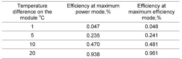
For the small temperature differences it is possible with good precision to consider that every degree of temperature difference provides: in the mode of the maximum power the efficiency ~ 0.047%, and in the mode of the maximum efficiency ~ 0.048% of the efficiency.
It should be noted, at increasing of average temperature the efficiency falls down (see Chapter 7). For example, in Chapter 4 it has been shown that at average temperature 300K by one degree of temperature difference the efficiency is about 0.05% (Table 4.1).
From Table 6.1 it follows that at a temperature slightly above (320K) – efficiency per one degree is slightly lower (~ 0.047%). It is explained by temperature dependences of thermoelectric material of the generators (Chapter 7, Fig. 7.3).
Heat flow density
At given efficiency the total converted power will be determined by heat flow Q c passing through the generator module. And it is set by the capacity of the heat source and the heat transport “capacity” (inverse of thermal resistance) of the generator itself. These characteristics must be coordinated.
Читать дальшеИнтервал:
Закладка:
Похожие книги на «Thermoelectric Microgenerators. Optimization for energy harvesting»
Представляем Вашему вниманию похожие книги на «Thermoelectric Microgenerators. Optimization for energy harvesting» списком для выбора. Мы отобрали схожую по названию и смыслу литературу в надежде предоставить читателям больше вариантов отыскать новые, интересные, ещё непрочитанные произведения.


Обсуждение, отзывы о книге «Thermoelectric Microgenerators. Optimization for energy harvesting» и просто собственные мнения читателей. Оставьте ваши комментарии, напишите, что Вы думаете о произведении, его смысле или главных героях. Укажите что конкретно понравилось, а что нет, и почему Вы так считаете.