Gennady Gromov - Thermoelectric Microgenerators. Optimization for energy harvesting
Здесь есть возможность читать онлайн «Gennady Gromov - Thermoelectric Microgenerators. Optimization for energy harvesting» — ознакомительный отрывок электронной книги совершенно бесплатно, а после прочтения отрывка купить полную версию. В некоторых случаях можно слушать аудио, скачать через торрент в формате fb2 и присутствует краткое содержание. ISBN: , Жанр: Физика, Прочая научная литература, на английском языке. Описание произведения, (предисловие) а так же отзывы посетителей доступны на портале библиотеки ЛибКат.
- Название:Thermoelectric Microgenerators. Optimization for energy harvesting
- Автор:
- Жанр:
- Год:неизвестен
- ISBN:978-5-4493-4334-5
- Рейтинг книги:3 / 5. Голосов: 1
-
Избранное:Добавить в избранное
- Отзывы:
-
Ваша оценка:
Thermoelectric Microgenerators. Optimization for energy harvesting: краткое содержание, описание и аннотация
Предлагаем к чтению аннотацию, описание, краткое содержание или предисловие (зависит от того, что написал сам автор книги «Thermoelectric Microgenerators. Optimization for energy harvesting»). Если вы не нашли необходимую информацию о книге — напишите в комментариях, мы постараемся отыскать её.
The structure of this book contains detailed explanations addressed to a wide range of readers, which for the most part are not specialists in the field of Thermoelectricity, the basic ideas, important aspects of the practical application of thermoelectric microgenerators in the in energy harvesting. I will be glad, if this book will serve as a reference tool in developing appropriate solutions.
Thermoelectric Microgenerators. Optimization for energy harvesting — читать онлайн ознакомительный отрывок
Ниже представлен текст книги, разбитый по страницам. Система сохранения места последней прочитанной страницы, позволяет с удобством читать онлайн бесплатно книгу «Thermoelectric Microgenerators. Optimization for energy harvesting», без необходимости каждый раз заново искать на чём Вы остановились. Поставьте закладку, и сможете в любой момент перейти на страницу, на которой закончили чтение.
Интервал:
Закладка:
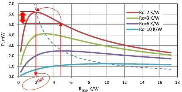
Figure. 5.2 Dependence of power P from thermal resistance of generator module Ȓ TEG at different thermal resistances of the rest of the system Ȓ c (paracitic thermal resistance). Here full temperature difference is ∆T s=10°C. Dotted line – power at zero parazitic thermal resistance – when the working temperature difference is a half (∆T=5° C).
In the case of thermal resistances optimization – maximum power is achieved with equal thermal resistance of working generator Ȓ' TEG and other (sum of parasitic) thermal resistances Ȓ c of the generator system.
Physical sense
Optimizing of thermal resistance has a simple physical meaning.
Generator works optimally if its heat transport capacity (thermal conductivity is inverse value to thermal resistance) and heat throughput of all other structural elements (primarily is the element responsible for heat -dissipation of past heat) agreed upon, namely, equal.
For simplicity we will consider only the element of heat dissipation – heat sink. If its heat transport capacity is less than similar parameter of generator module, less heat passes through the system as a whole the generator converts less efficient.
On the other hand, the smaller thermal resistance of heat sink is better. And generator with the specified thermal resistance works better (example, Figure 5.1 – up arrow). But then already the generator will “brake” heat flow, as its thermal resistance becomes higher than of the heat sink.
For smaller thermal resistance of heat transport, there is a different, more optimal generator that will produce even more power (Figure 5.1 – red arrow sideways). But such more optimal thermal resistance of the generator should be smaller. So according to (5.17) and Fig.5.2 it should correspond to thermal resistance of the heat exchange element (Fig. 5.1 – red down arrow).
Particular solutions
Note that maximum power is achieved when there is no loss in generator on parasitic thermal resistances. This is a particular (ideal) case when the full temperature difference drops on the generator module:
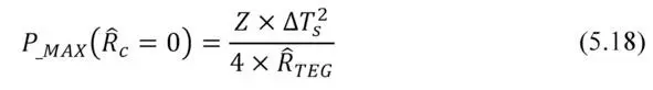
In real system with finite parasitic thermal resistance (then Δ T <���Δ T s ), the maximal available output power is 4 times (!) less than the maximum power output under ideal conditions.
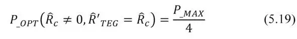
In a case of non-zero parasitic thermal resistance the optimal case is the equality Ȓ’ TEG=Ȓ c . This is equivalent to the ideal case of half temperature difference on the generator module (Δ T = ½ Δ T s ). The dependence of the power from the temperature difference is quadratic. This explains the ¼ of the optimum output power (5.18—5.19).
The construction of thermoelectric generators allows quite easily manage their thermal resistance. Namely, to obtain the optimal solution for the thermal resistance (thermal resistance change) there is a direct way to change the height and/or cross-sections of thermoelements of generator module.
Heat runs directly in thermoelectric generator through the thermoelements. Their thermal resistance is fundamental in the total thermal resistance of TE generator. Therefore, variation in height and cross section of thermoelements allows optimizing thermal resistance of the TE generator for maximum efficiency.
Thermal resistance of working generator
It must be noted that in the working generator module the effective thermal resistance, namely, the ratio of temperature difference to transported heat power differs from the thermal resistance related to the heat conductivity (Chapter 2). And approach of optimization on thermal resistance needs to be applied to the effective thermal resistance, i.e. taking into account ratios (2.24) – (2.26).
In contrast to thermal resistance of thermal conductivity Ȓ TEG the effective thermal resistance Ȓ’ TEG of working thermoelectric generator depends on the operating mode (2.28).
– When an open electrical circuit the m=∞ and Ȓ’ TEG=Ȓ TEG.
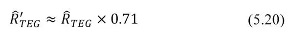
– At maximum efficiency mode the value m opt≈ 1.4 is given by the expression (4.2). If ZT≈ 1, the effective thermal resistance Ȓ’ TEG turns out to be approximately 29% less then thermal resistance of thermal conductivity Ȓ TEG .
– In maximum power mode m= 1 and the effective thermal resistance of approximately a third less than Ȓ TEG .
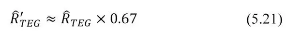
Since the heat resistances at maximum power (5.20) and maximum efficiency (5.21) modes differ slightly, it is often convenient to perform all calculations and modeling for maximum power mode with m =1.
Chapter 6. Design optimization
Summary.In this Chapter dependences of parameters of thermoelectric generators on elements of their design are considered. The analysis is provided on the example of the known wide nomenclature range of microgenerator modules. On these examples it is given an idea, what parameters of generators and what role they play in their efficiency and in consumer properties.
Introduction
Useful formulas are illustrated on the example of series of standard TE microgenerators developed earlier [5] in the TEC Microsystems GmbH company in relation to tasks of “low power” – energy harvesting applications.
The nomenclature of thermoelectric modules of TEC Microsystems GmbH is developed with use of classification system of thermoelectric micromodules [6]. This classification allows systematizing thermoelectric micromodules on series in compliance with their parameters and features of a design (see also Chapter 12).
Thus, logical ranks of micromodules convenient for their choice for practical applications are created.
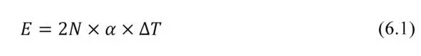
Number of thermoelements
The number of thermoelements 2N in the generator module at the specified temperature difference ∆ T and Seebeck coefficient α determines the key characteristic – total thermoEMF E .
The value of thermoEMF E provided by the generator determines the output voltage U in the load circuit.
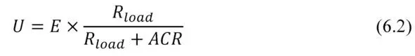
Depending on value of load resistance R load the working voltage U range of generator could vary widely.
In maximum power mode
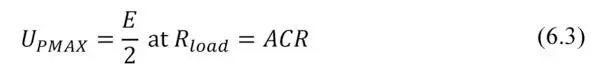
If to increase load resistance Rload in the limit we have
Читать дальшеИнтервал:
Закладка:
Похожие книги на «Thermoelectric Microgenerators. Optimization for energy harvesting»
Представляем Вашему вниманию похожие книги на «Thermoelectric Microgenerators. Optimization for energy harvesting» списком для выбора. Мы отобрали схожую по названию и смыслу литературу в надежде предоставить читателям больше вариантов отыскать новые, интересные, ещё непрочитанные произведения.


Обсуждение, отзывы о книге «Thermoelectric Microgenerators. Optimization for energy harvesting» и просто собственные мнения читателей. Оставьте ваши комментарии, напишите, что Вы думаете о произведении, его смысле или главных героях. Укажите что конкретно понравилось, а что нет, и почему Вы так считаете.