Gennady Gromov - Thermoelectric Microgenerators. Optimization for energy harvesting
Здесь есть возможность читать онлайн «Gennady Gromov - Thermoelectric Microgenerators. Optimization for energy harvesting» — ознакомительный отрывок электронной книги совершенно бесплатно, а после прочтения отрывка купить полную версию. В некоторых случаях можно слушать аудио, скачать через торрент в формате fb2 и присутствует краткое содержание. ISBN: , Жанр: Физика, Прочая научная литература, на английском языке. Описание произведения, (предисловие) а так же отзывы посетителей доступны на портале библиотеки ЛибКат.
- Название:Thermoelectric Microgenerators. Optimization for energy harvesting
- Автор:
- Жанр:
- Год:неизвестен
- ISBN:978-5-4493-4334-5
- Рейтинг книги:3 / 5. Голосов: 1
-
Избранное:Добавить в избранное
- Отзывы:
-
Ваша оценка:
Thermoelectric Microgenerators. Optimization for energy harvesting: краткое содержание, описание и аннотация
Предлагаем к чтению аннотацию, описание, краткое содержание или предисловие (зависит от того, что написал сам автор книги «Thermoelectric Microgenerators. Optimization for energy harvesting»). Если вы не нашли необходимую информацию о книге — напишите в комментариях, мы постараемся отыскать её.
The structure of this book contains detailed explanations addressed to a wide range of readers, which for the most part are not specialists in the field of Thermoelectricity, the basic ideas, important aspects of the practical application of thermoelectric microgenerators in the in energy harvesting. I will be glad, if this book will serve as a reference tool in developing appropriate solutions.
Thermoelectric Microgenerators. Optimization for energy harvesting — читать онлайн ознакомительный отрывок
Ниже представлен текст книги, разбитый по страницам. Система сохранения места последней прочитанной страницы, позволяет с удобством читать онлайн бесплатно книгу «Thermoelectric Microgenerators. Optimization for energy harvesting», без необходимости каждый раз заново искать на чём Вы остановились. Поставьте закладку, и сможете в любой момент перейти на страницу, на которой закончили чтение.
Интервал:
Закладка:
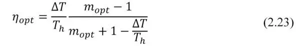
Where the optimum ratio of load and internal resistances m opt ( m opt=R load/ACR ) can be expressed as the following.
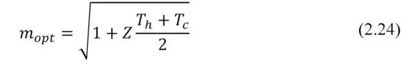
Note, please, the formula (2.24). If maximum power P max converted by generator can be achieved when m =1, then maximum efficiency η – at other value of this ratio – m opt (2.24). In the thermoelectric generator, as in any heat engine, maximum power mode operation differs from mode of maximum efficiency.
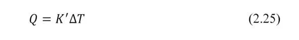
Effective thermal conductivity and thermal resistance
Heat Q passed through a media, which is the generator, one can write in general using the effective thermal conductivity K” of this media and temperature difference Δ T as the following.
In working generator the heat is Q c (2.12), which differs from the heat transported due to “simple” thermal conductivity Q λ:
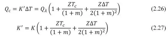
Effective thermal conductivity K” differs from conventional thermal conductivity K of agenerator due to the additional Peltier and Joule heat flows, that appear in the working generator, and which are superimposed on the conventional thermal conductivity (Fig. 2.2).
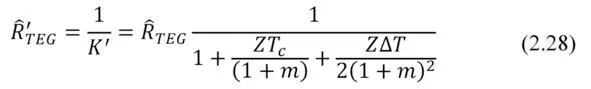
Thermal resistance of the working generator Ȓ’ TEG is the following
To a first approximation, at small temperature differences Δ T the 3-rd member (Joule) in the sum in brackets (2.27) can be ignored. Indeed, it can be shown that contribution of this term at small temperature differences is small, no more than 0.5—1%.
Then
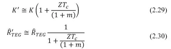
Exclusion of a member, depending on Δ T dramatically simplifies analysis of a thermoelectric generator in the tasks of complex ambient. Where the generator is placed between other media and interfaces with different thermal resistance, and it is desirable to optimize the thermal resistance Ȓ’ TEG of the working generator (see Chapter 5).
When open electrical circuit takes place in the generator, then there is no Peltier and no Joule heat flows. Only thermal conductivity heat flow takes place. In other words, then R load=∞ and m=∞ then the formula (2.26) is simplified to:
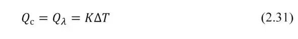
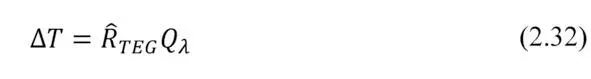
Temperature difference Δ T at a generator module when an open circuit takes place is associated with heat flow of thermal contuctivity Q λ as the following.
Chapter 3. Optimization of electrical circuit
Preface. Thermoelectric generator transforms thermal energy and gives it to external electric circuit. Here coordination of elements of the electric circuit with parameters of the generator is essential for extraction of maximum power. In this Chapter questions of optimization of the electric circuit are considered.
Basic formulas
Simplified electrical circuit of a generator module is shown in Fig.3.1.
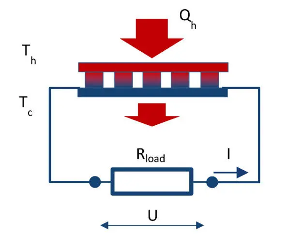
Figure. 3.1 Schematics of thermoelectric generator.
Maximum electric power transformed by a generator from heat source is defined by thermoEMF E and internal resistance ACR of the generator.
The thermoEMF E is found as the following
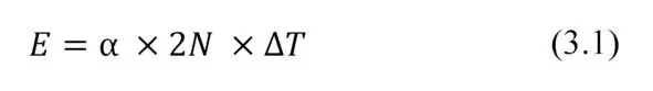
where α – thermoelectric coefficient (Seebeck coefficient) of pair of thermoelements n- and p-types; 2N – number of elements in generator module; Δ T -working temperature difference on generator module ( Δ T=T h-T c).
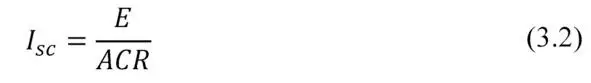
If to short the electric circuit of the generator ( R load= 0), the short-circuit current I sc is
At short-circuit the power P sc allocated in the electric circuit is maximal.
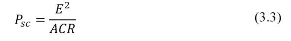
However, all this power will be converted into Joule heat in thermoelements of the generator. In fact, heat converted into electric current returns again into the heat. There is no useful work.
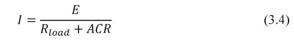
A generator performs useful work when converted power is given out to the external load that has electrical resistance different from zero ( R load> 0) .
Then the working current I in the electric circuit (Fig. 3.1) is
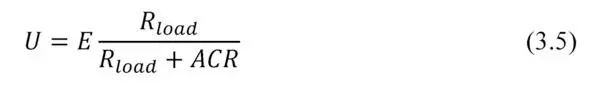
Voltage U in the electric circuit, correspondingly
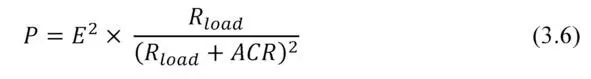
Formula of the net power P has the following form:
Maximum power
From equation (3.6) it follows that the generated power P nonlinearly dependends on the load resistance R load .
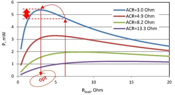
Figure. 3.2 Sample dependence of generator power (four variants by ACR) from the load resistance. Temperature difference 5°C.
This dependence has maximum power P max when external load resistance R load is equal to internal resistance ACR of the generator ( R load=ACR):
– At given internal resistance ACR of generator, there is an optimal load resistance R load in terms of maximum power conversion.
Читать дальшеИнтервал:
Закладка:
Похожие книги на «Thermoelectric Microgenerators. Optimization for energy harvesting»
Представляем Вашему вниманию похожие книги на «Thermoelectric Microgenerators. Optimization for energy harvesting» списком для выбора. Мы отобрали схожую по названию и смыслу литературу в надежде предоставить читателям больше вариантов отыскать новые, интересные, ещё непрочитанные произведения.


Обсуждение, отзывы о книге «Thermoelectric Microgenerators. Optimization for energy harvesting» и просто собственные мнения читателей. Оставьте ваши комментарии, напишите, что Вы думаете о произведении, его смысле или главных героях. Укажите что конкретно понравилось, а что нет, и почему Вы так считаете.