Gennady Gromov - Thermoelectric Microgenerators. Optimization for energy harvesting
Здесь есть возможность читать онлайн «Gennady Gromov - Thermoelectric Microgenerators. Optimization for energy harvesting» — ознакомительный отрывок электронной книги совершенно бесплатно, а после прочтения отрывка купить полную версию. В некоторых случаях можно слушать аудио, скачать через торрент в формате fb2 и присутствует краткое содержание. ISBN: , Жанр: Физика, Прочая научная литература, на английском языке. Описание произведения, (предисловие) а так же отзывы посетителей доступны на портале библиотеки ЛибКат.

- Название:Thermoelectric Microgenerators. Optimization for energy harvesting
- Автор:
- Жанр:
- Год:неизвестен
- ISBN:978-5-4493-4334-5
- Рейтинг книги:3 / 5. Голосов: 1
-
Избранное:Добавить в избранное
- Отзывы:
-
Ваша оценка:
Thermoelectric Microgenerators. Optimization for energy harvesting: краткое содержание, описание и аннотация
Предлагаем к чтению аннотацию, описание, краткое содержание или предисловие (зависит от того, что написал сам автор книги «Thermoelectric Microgenerators. Optimization for energy harvesting»). Если вы не нашли необходимую информацию о книге — напишите в комментариях, мы постараемся отыскать её.
The structure of this book contains detailed explanations addressed to a wide range of readers, which for the most part are not specialists in the field of Thermoelectricity, the basic ideas, important aspects of the practical application of thermoelectric microgenerators in the in energy harvesting. I will be glad, if this book will serve as a reference tool in developing appropriate solutions.
Thermoelectric Microgenerators. Optimization for energy harvesting — читать онлайн ознакомительный отрывок
Ниже представлен текст книги, разбитый по страницам. Система сохранения места последней прочитанной страницы, позволяет с удобством читать онлайн бесплатно книгу «Thermoelectric Microgenerators. Optimization for energy harvesting», без необходимости каждый раз заново искать на чём Вы остановились. Поставьте закладку, и сможете в любой момент перейти на страницу, на которой закончили чтение.
Интервал:
Закладка:
Here you can make an important note about the maximum possible efficiency for any heat engines used in waste heat recycling applications (energy harvesting).
Namely, the ideal heat engine working by Carnot cycle near room temperature provides efficiency only about 0.33% per degree of temperature difference (4.11).
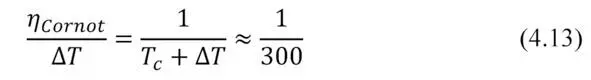
Thus, this is the absolute maximum.
According to Carnot’s theorem, such wording [22]:
“Maximum efficiency of any heat engine may not exceed the efficiency of Carnot heat engine, running at the same temperatures of the heater and cooler.
This is an important point to general understand. To avoid posing unrealistic tasks to retrieve large efficiency with thermoelectric generators – larger than limited by the ideal Carnot cycle.
This issue will be discussed further in Chapter 7.
Chapter 5. Optimization of thermal resistance
Introduction.In this Chapter optimization of use of thermoelectric generator by coordination of thermal resistance of elements of design of the generator device are considered. As it appears, coordination on thermal resistance is in many respects similar to coordination of electric load resistance. Namely, there is an optimal solution with maximum efficiency at a certain ratio of thermal resistance of the generator module and other elements of a design.
Thermal resistance
Working parameters of a thermoelectric generator is determined by temperature difference ∆ T that is created when heat is passing through the generator.
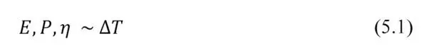
In basic formulas for thermoEMF E , efficiency η and net power P the working temperature difference ∆ T is mentioned that is created directly on the sides (hot and cold) of the generator module.
In practice, however, this working ∆ T is less than total temperature difference ∆ T s that is created at generator device by heat source relating to the envirnment, where heat is dissipated (Figure 5.1).
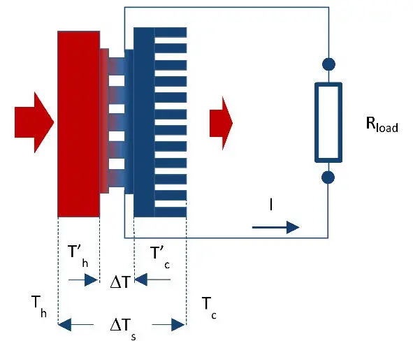
Figure. 5.1 Simplified schema of generator device in working arrangement with interfaces and heat sink.
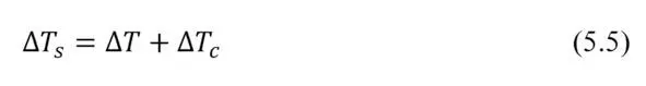
Total temperature difference:
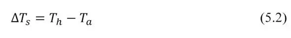
where T h – temperature of heat source; T a – ambient temperature.
Working (net) temperature difference ∆ T on generator module is always less than total value ∆ T s :
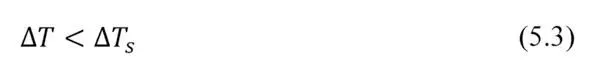
This is due to the fact that in the design with thermoelectric generator inevitable parasitic thermal contact resistance at the crossings of the design. Particularly thermal resistance of heat sink is most important, the heat which dissipates into the surrounding ambient (Fig. 5.1).
In general
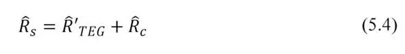
where Ȓ s – total thermal resistance of generator device; Ȓ’ TEG – thermal resistance of working thermoelectric generator module; Ȓ c -thermal resistances other items of the generator device.
Presence of parasitic thermal resistances Ȓ c besides total thermal resistance of generator device Ȓ s reduces working temperature difference ∆ T on TE generator module in relation to the total difference ∆ T s and, consequently, reduces its effectiveness.
Taking into account formulas (2.24) and (2.25)
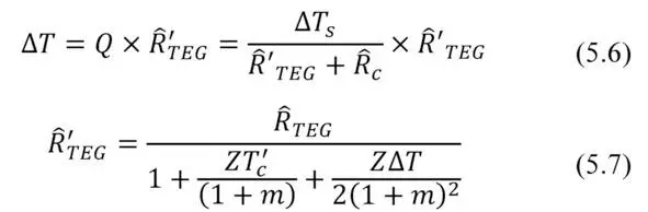
where T’ C – temperature on cold side of thermoelectric generator; Ȓ TEG – thermal resistance of thermal conductivity of the thermoelectric generator.
In practical tasks, you must always strive to reduce parasitic heat resistance of construction, because it means a loss of working temperature difference and correspondingly – efficiency of generator.
However, as there is always non-zero values of such losses ( Ȓ c> 0 ) it is necessary an approach of optimization – the search for an optimal balance of these values Ȓ’ TEG and Ȓ c
Net power
Consider net power P converted by thermoelectric generator.
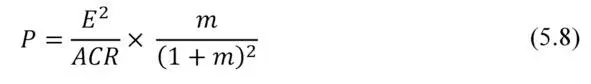
where ACR – internal resistance of thermoelectric generator; m – ratio of resistances: external electrical load to internal resistance of the generator.
Here
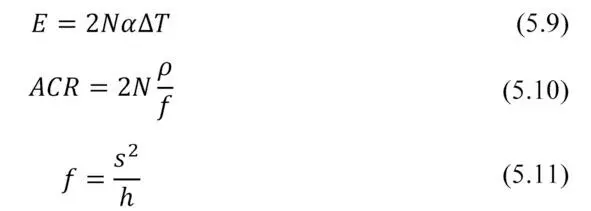
where f – thermoelement form-factor (ratio of cross-section to height); p – electrical resistivity of thermoelement material; a -thermoelectric coefficient (Seebeck coefficient) of thermoelectric material of thermoelement; N – number of pairs of thermoelements.
Then
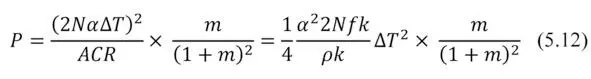
With
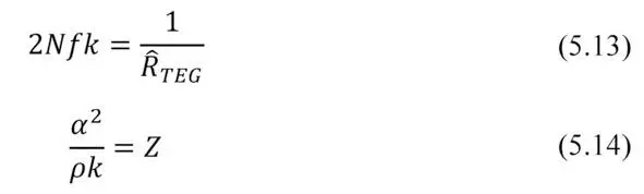
where k -thermal conductivity of thermoelement; Z – Figure of Merit.
Then the desired dependency of net power conversion P from the thermal resistance is:
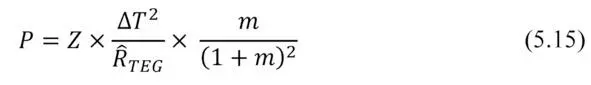
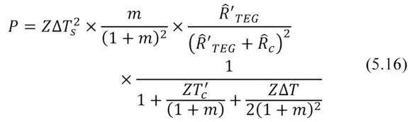
Where given (5.6) and (5.7) the total dependence of net power P on heat resistance for full temperature difference ∆ T s the system is as follows.
Maximum power
Maximum power P max is a particular case of the above general formula (5.16), namely, at m= 1. The expression for maximum power P max has the following form
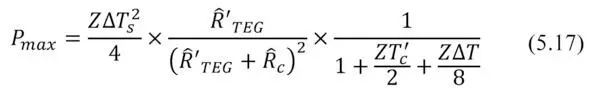
The formula (5.17) and graphical view (Fig. 5.2) for maximum output power P max from the thermal resistance Ȓ' TEG of the working generator is similar to the dependence of the power from the electrical resistance (Fig. 3.1). Namely, in both cases there are local maximums of power.
Читать дальшеИнтервал:
Закладка:
Похожие книги на «Thermoelectric Microgenerators. Optimization for energy harvesting»
Представляем Вашему вниманию похожие книги на «Thermoelectric Microgenerators. Optimization for energy harvesting» списком для выбора. Мы отобрали схожую по названию и смыслу литературу в надежде предоставить читателям больше вариантов отыскать новые, интересные, ещё непрочитанные произведения.


Обсуждение, отзывы о книге «Thermoelectric Microgenerators. Optimization for energy harvesting» и просто собственные мнения читателей. Оставьте ваши комментарии, напишите, что Вы думаете о произведении, его смысле или главных героях. Укажите что конкретно понравилось, а что нет, и почему Вы так считаете.