Ibrahim Dogan - Advanced PIC Microcontroller Projects in C
Здесь есть возможность читать онлайн «Ibrahim Dogan - Advanced PIC Microcontroller Projects in C» весь текст электронной книги совершенно бесплатно (целиком полную версию без сокращений). В некоторых случаях можно слушать аудио, скачать через торрент в формате fb2 и присутствует краткое содержание. Город: Burlington, Год выпуска: 2008, ISBN: 2008, Издательство: Elsevier Ltd, Жанр: Программирование, Компьютерное железо, на английском языке. Описание произведения, (предисловие) а так же отзывы посетителей доступны на портале библиотеки ЛибКат.

- Название:Advanced PIC Microcontroller Projects in C
- Автор:
- Издательство:Elsevier Ltd
- Жанр:
- Год:2008
- Город:Burlington
- ISBN:978-0-7506-8611-2
- Рейтинг книги:5 / 5. Голосов: 1
-
Избранное:Добавить в избранное
- Отзывы:
-
Ваша оценка:
Advanced PIC Microcontroller Projects in C: краткое содержание, описание и аннотация
Предлагаем к чтению аннотацию, описание, краткое содержание или предисловие (зависит от того, что написал сам автор книги «Advanced PIC Microcontroller Projects in C»). Если вы не нашли необходимую информацию о книге — напишите в комментариях, мы постараемся отыскать её.
• Features 20 complete, tried and test projects
• Includes a CD-ROM of all the programs, hex listings, diagrams, and data sheets
Advanced PIC Microcontroller Projects in C — читать онлайн бесплатно полную книгу (весь текст) целиком
Ниже представлен текст книги, разбитый по страницам. Система сохранения места последней прочитанной страницы, позволяет с удобством читать онлайн бесплатно книгу «Advanced PIC Microcontroller Projects in C», без необходимости каждый раз заново искать на чём Вы остановились. Поставьте закладку, и сможете в любой момент перейти на страницу, на которой закончили чтение.
Интервал:
Закладка:
void Str_To_Usart(unsigned char *m, unsigned char l) {
unsigned char i;
unsigned char txt[4];
i=0;
for(i=0; i
ByteToStr(m[i],txt);
Text_To_Usart(txt);
Space();
}
}
//
// Start of MAIN program
//
void main() {
unsigned char error,CID[16];
unsigned char msg[] = " SD CARD CID REGISTER";
//
// Configure the serial port
//
Soft_Uart_Init(PORTC,7,6,2400,0); // TX=RC6
//
// Initialize the SD card
//
Spi_Init_Advanced(MASTER_OSC_DIV16, DATA_SAMPLE_MIDDLE,
CLK_IDLE_LOW, LOW_2_HIGH);
//
// Initialize the SD bus
//
while(Mmc_Init(&PORTC,2));
//
// Start of MAIN loop. Read the SD card CID register and send the data
// to serial port every 10 seconds
//
for(;;) // Endless loop
{
Text_To_Usart(msg); // Send TEXT
Newline(); // Send newline
Newline(); // Send newline
error = Mmc_Read_Cid(CID); // Read CID register into CID
//
// Send the data to RS232 port
//
Str_To_Usart(CID,16); // Send CID contents to UART
Delay_Ms(10000); // Wait 10 seconds
Newline();
Newline();
}
}

Figure 7.9: Program listing
Variable msg is loaded with the message that is to be displayed when power is applied to the system. Then the UART is initialized at PORTC with a baud rate of 2400.
Before the SD card library functions are used, the function Spi_Init_Advanced must be called with the given arguments. Then the SD card bus is initialized by calling function Mmc_Init , where it is specified that the card is connected to PORTC. The program then enters an endless loop that repeats every ten seconds. Inside this loop the heading message is displayed followed by two new-line characters. The program then reads the contents of register CID by calling function Mmc_Read_Cid and stores the data in character array CID . The data is then sent to the serial port by calling function Str_To_Usart . At the end of the loop two new-line characters are displayed, the program waits for ten seconds, and the loop is repeated.
The operation of the project can be tested by connecting the device to a PC and starting the HyperTerminal terminal emulation program on the PC. Set the communications parameters to 2400 baud, 8 data bits, 1 stop bit, and no parity bit. An example output on the screen is shown in Figure 7.10.
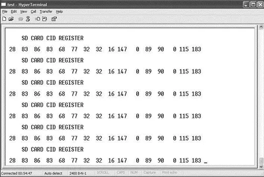
Figure 7.10: An example output from the project on HyperTerminal
The data returned by the card is:
28 83 86 83 68 77 32 32 16 147 0 89 90 0 115 183
Referring to Table 7.3, we can say the following about this card:
Manufacturer ID = 28 decimal
OEM/Application ID = SV
Product Name = SDM
Product Revision = 1.0 (decimal 16 corresponds to binary “0001 0000” which is 10 in BCD; the revision number is as n.m, giving 1.0)
Serial Number = 16 147 0 89 decimal
Reserved = “0000” bits (4 bits only)
Manufacture Date Code = 073 (this 12-bit parameter has the binary value “0000 0111 0011” where the upper 4 bits are derived from the lower 4 bits of the reserved field and the lower 8 bits are decimal 115. This gives BCD value 073. The date is in YYM format since 2000. Thus, this card was manufactured in 2007, March).
CRC = “1011100” binary (the LSB bit is always 1)
PROJECT 7.2 — Read/Write to SD Card Sectors
The hardware of this project is the same as for Project 7.1 (i.e., as shown in Figure 7.8). In this project, sector 10 of the SD card is filled with “C” characters, and then this sector is read and the card data is sent to the UART.
The program listing of this project is given in Figure 7.11 (program SD2.C). Two character arrays called data1 and data2 , of 512 bytes each, are declared at the beginning of the program. Array data1 is loaded with character “C,” and the contents of this array are written to sector 10 of the SD card. Then the contents of sector 10 are read into character array data2 and sent to the UART, displaying 512 “C” characters on the PC screen. Normally, only one array is used to read and write to the SD card. Two arrays are used here to make it clear that what is sent to the UART is the card data, not the contents of array data1 .
/**************************************************************
SD CARD PROJECT
===============
In this project a SD card is connected to PORTC as follows:
CS RC2
CLK RC3
DO RC4
DI RC5
In addition, a MAX232 type RS232 voltage level converter chip
is connected to serial output port RC6.
The program loads sector 10 of the SD card with character "C".
The contents of sector 10 is then read and sent to the UART,
displaying 512 "C" characters on the PC display.
Author: Dogan Ibrahim
Date: August 2007
File: SD2.C
**************************************************************/
unsigned char data1[512],data2[512];
unsigned int i;
unsigned short x;
void main() {
//
// Configure the serial port
//
Usart_Init(2400);
//
// Initialize the SD card
// Spi_Init_Advanced(MASTER_OSC_DIV16, DATA_SAMPLE_MIDDLE, CLK_IDLE_LOW, LOW_2_HIGH);
//
// Initialize the SD bus
//
while(Mmc_Init(&PORTC,2));
//
// Fill buffer with character "C"
//
for(i=0; i<512; i++) data1[i] = 'C';
//
// Write to sector 10
//
x = Mmc_Write_Sector(10, data1);
//
// Now read from sector 10 into data2 and send to UART
//
x = Mmc_Read_Sector(10,data2);
for(i=0; i<400; i++) Usart_Write(data2[i]); // Send to UART
for(;;); // Wait here forever
}
Figure 7.11: Program listing of the project
PROJECT 7.3 — Using the Card Filing System
The hardware of this project is the same as for Project 7.1 (i.e., as shown in Figure 7.8). In this project, a file called MYFILE55.TXT is created on the SD card. String “This is MYFILE.TXT” is written to the file initially. Then the string “This is the added data…” is appended to the file. The program then reads the contents of the file and sends the string “This is MYFILE.TXT. This is the added data…” to the UART, enabling the data to be displayed on the PC screen when HyperTerminal is run.
Читать дальшеИнтервал:
Закладка:
Похожие книги на «Advanced PIC Microcontroller Projects in C»
Представляем Вашему вниманию похожие книги на «Advanced PIC Microcontroller Projects in C» списком для выбора. Мы отобрали схожую по названию и смыслу литературу в надежде предоставить читателям больше вариантов отыскать новые, интересные, ещё непрочитанные произведения.


Обсуждение, отзывы о книге «Advanced PIC Microcontroller Projects in C» и просто собственные мнения читателей. Оставьте ваши комментарии, напишите, что Вы думаете о произведении, его смысле или главных героях. Укажите что конкретно понравилось, а что нет, и почему Вы так считаете.