Ibrahim Dogan - Advanced PIC Microcontroller Projects in C
Здесь есть возможность читать онлайн «Ibrahim Dogan - Advanced PIC Microcontroller Projects in C» весь текст электронной книги совершенно бесплатно (целиком полную версию без сокращений). В некоторых случаях можно слушать аудио, скачать через торрент в формате fb2 и присутствует краткое содержание. Город: Burlington, Год выпуска: 2008, ISBN: 2008, Издательство: Elsevier Ltd, Жанр: Программирование, Компьютерное железо, на английском языке. Описание произведения, (предисловие) а так же отзывы посетителей доступны на портале библиотеки ЛибКат.

- Название:Advanced PIC Microcontroller Projects in C
- Автор:
- Издательство:Elsevier Ltd
- Жанр:
- Год:2008
- Город:Burlington
- ISBN:978-0-7506-8611-2
- Рейтинг книги:5 / 5. Голосов: 1
-
Избранное:Добавить в избранное
- Отзывы:
-
Ваша оценка:
Advanced PIC Microcontroller Projects in C: краткое содержание, описание и аннотация
Предлагаем к чтению аннотацию, описание, краткое содержание или предисловие (зависит от того, что написал сам автор книги «Advanced PIC Microcontroller Projects in C»). Если вы не нашли необходимую информацию о книге — напишите в комментариях, мы постараемся отыскать её.
• Features 20 complete, tried and test projects
• Includes a CD-ROM of all the programs, hex listings, diagrams, and data sheets
Advanced PIC Microcontroller Projects in C — читать онлайн бесплатно полную книгу (весь текст) целиком
Ниже представлен текст книги, разбитый по страницам. Система сохранения места последней прочитанной страницы, позволяет с удобством читать онлайн бесплатно книгу «Advanced PIC Microcontroller Projects in C», без необходимости каждый раз заново искать на чём Вы остановились. Поставьте закладку, и сможете в любой момент перейти на страницу, на которой закончили чтение.
Интервал:
Закладка:
Table 7.7: Size of the security protected area and the user area in a DOS-formatted card
| Model | Protected area (sectors) | User area (sectors) |
|---|---|---|
| SDSDB-16 | 39 | 28,704 |
| SDSDB-32 | 45 | 59,680 |
| SDSDJ-64 | 57 | 121,760 |
| SDSDJ-128 | 95 | 245,824 |
| SDSDJ-256 | 155 | 493,824 |
| SDSDJ-512 | 275 | 990,352 |
| SDSDJ-1024 | 519 | 1,982,976 |
1 sector = 512 bytes.
A card can be inserted and removed from the bus without any damage. This is because all data transfer operations are protected by cyclic redundancy check (CRC) codes, and any bit changes caused by inserting or removing a card can easily be detected. SD cards typically operate with a supply voltage of 2.7V. The maximum allowed power supply voltage is 3.6V. If the card is to be operated from a standard 5.0V supply, a voltage regulator should be used to drop the voltage to 2.7V.
Using an SD card requires the card to be inserted into a special card holder with external contacts (see Figure 7.6) so connections are easily made to the required card pins.
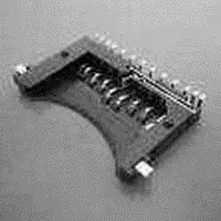
Figure 7.6: SD card holder
7.2 mikroC Language SD Card Library Functions
The mikroC language provides an extensive set of library functions to read and write data to SD cards (and also MultiMediaCards, MMC). Data can be written to or read from a given sector of the card, or the file system on the card can be used for more sophisticated applications.
The following library functions are provided:
• Mmc_Init (initialize the card)
• Mmc_Read_Sector (read one sector of data)
• Mmc_Write_Sector (write one sector of data)
• Mmc_Read_Cid (read CID register)
• Mmc_Read_Csd (read CSD register)
• Mmc_Fat_Init (initialize FAT)
• Mmc_Fat_QuickFormat (format the card to FAT16)
• Mmc_Fat_Assign (assign the file we will be working with)
• Mmc_Fat_Reset (reset the file pointer; opens the currently assigned file for reading)
• Mmc_Fat_Rewrite (reset the file pointer and clear assigned file; opens the assigned file for writing)
• Mmc_Fat_Append (move file pointer to the end of assigned file so new data can be appended to the file)
• Mmc_Fat_Read (read the byte the file pointer points to)
• Mmc_Fat_Write (write a block of data to the assigned file)
• Mmc_Set_File_Date (write system timestamp to a file)
• Mmc_Fat_Delete (delete a file)
• Mmc_Fat_Get_File_Date (read file timestamp)
• Mmc_Fat_Get_File_Size (get file size in bytes)
• Mmc_Fat_Get_Swap_File (create a swap file)
In the remainder of this chapter we will look at some SD-card and PIC18 microcontroller-based projects.
PROJECT 7.1 — Read CID Register and Display on a PC Screen
In this project a SD card is interfaced to a PIC18F452-type microcontroller. The serial output port of the microcontroller is connected to the serial input port (e.g., COM1) of a PC. The microcontroller reads the contents of the card CID register and sends this data to the PC so it can be displayed on the PC screen.
Figure 7.7 shows the block diagram of the project.
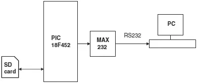
Figure 7.7: Block diagram of the project
The circuit diagram of the project is shown in Figure 7.8. The SD card is inserted into a card holder and then connected to PORTC of a PIC18F452 microcontroller through 2.2K and 3.3K resistors, using the following pins:
• Card CS to PORTC pin RC2
• Card CLK to PORTC pin RC3
• Card DO to PORTC pin RC4
• Card DI to PORTC pin RC5
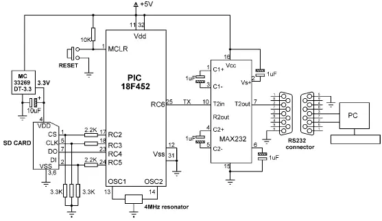
Figure 7.8: Circuit diagram of the project
According to the SD card specifications, when the card is operating with a supply voltage of VDD = 3.3V, the input-output pin voltage levels are as follows:
• Minimum produced output HIGH voltage, VOH = 2.475V
• Maximum produced output LOW voltage, VOL = 0.4125V
• Minimum required input HIGH voltage, VIH = 2.0625
• Maximum input HIGH voltage, VIH = 3.6V
• Maximum required input LOW voltage, VIL = 0.825V
Although the output produced by the card (2.475V) is sufficient to drive the input port of a PIC microcontroller, the logic HIGH output of the microcontroller (about 4.3V) is too high for the SD card inputs (maximum 3.6V). Therefore, a potential divider is set up at the three inputs of the SD card using 2.2K and 3.3K resistors. This limits the maximum voltage at the inputs of the SD card to about 2.5V:
SD card input voltage = 4.3V × 3.3K/(2.2K + 3.3K) = 2.48V
Serial output port pin RC6 (TX) of the microcontroller is connected to a MAX232-type RS232 voltage level converter chip and then to a 9-way D-type connector so it can be connected to the serial input port of a PC.
The microcontroller is powered from a 5V supply which is obtained via a 7805-type 5V regulator with a 9V input. The 2.7V–3.6V supply required by the SD card is obtained via an MC33269DT-3.3 regulator with 3.3V output and is driven from the 5V input voltage.
The program listing of the project is given in Figure 7.9 (program SD1.C). At the beginning of the main program, character array CID is declared to have 16 bytes.
/**************************************************************
SD CARD PROJECT
===============
In this project a SD card is connected to PORTC as follows:
CS RC2
CLK RC3
DO RC4
DI RC5
In addition, a MAX232 type RS232 voltage level converter chip is
connected to serial output port RC6.
The program reads the SD card CID register parameters and
sends it to a PC via the serial interface. This process is
repeated at every 10 seconds.
The UART is set to operate at 2400 Baud, 8 bits, no parity.
Author: Dogan Ibrahim
Date: August 2007
File: SD1.C
**************************************************************/
//
// This function sends carriage-return and line-feed to USART
//
void Newline() {
Soft_Uart_Write(0x0D); // Send carriage-return
Soft_Uart_Write(0x0A); // Send line-feed
}
//
// This function sends a space character to USART
//
void Space() {
Soft_Uart_Write(0x20);
}
//
// This function sends a text to serial port
//
void Text_To_Usart(unsigned char *m) {
unsigned char i;
i = 0;
while(m[i] != 0) { // Send TEXT to serial port
Soft_Uart_Write(m[i]);
i++;
}
}
//
// This function sends string to serial port. The string length is passed as
// an argument
//
Интервал:
Закладка:
Похожие книги на «Advanced PIC Microcontroller Projects in C»
Представляем Вашему вниманию похожие книги на «Advanced PIC Microcontroller Projects in C» списком для выбора. Мы отобрали схожую по названию и смыслу литературу в надежде предоставить читателям больше вариантов отыскать новые, интересные, ещё непрочитанные произведения.


Обсуждение, отзывы о книге «Advanced PIC Microcontroller Projects in C» и просто собственные мнения читателей. Оставьте ваши комментарии, напишите, что Вы думаете о произведении, его смысле или главных героях. Укажите что конкретно понравилось, а что нет, и почему Вы так считаете.