Qing Li - Real-Time Concepts for Embedded Systems
Здесь есть возможность читать онлайн «Qing Li - Real-Time Concepts for Embedded Systems» весь текст электронной книги совершенно бесплатно (целиком полную версию без сокращений). В некоторых случаях можно слушать аудио, скачать через торрент в формате fb2 и присутствует краткое содержание. Город: San Francisco, Год выпуска: 2003, ISBN: 2003, Издательство: CMP books, Жанр: ОС и Сети, на английском языке. Описание произведения, (предисловие) а так же отзывы посетителей доступны на портале библиотеки ЛибКат.
- Название:Real-Time Concepts for Embedded Systems
- Автор:
- Издательство:CMP books
- Жанр:
- Год:2003
- Город:San Francisco
- ISBN:1-57820-124-1
- Рейтинг книги:4 / 5. Голосов: 1
-
Избранное:Добавить в избранное
- Отзывы:
-
Ваша оценка:
Real-Time Concepts for Embedded Systems: краткое содержание, описание и аннотация
Предлагаем к чтению аннотацию, описание, краткое содержание или предисловие (зависит от того, что написал сам автор книги «Real-Time Concepts for Embedded Systems»). Если вы не нашли необходимую информацию о книге — напишите в комментариях, мы постараемся отыскать её.
Delve into the details of real-time programming so you can develop a working knowledge of the common design patterns and program structures of real-time operating systems (RTOS). The objects and services that are a part of most RTOS kernels are described and real-time system design is explored in detail. You learn how to decompose an application into units and how to combine these units with other objects and services to create standard building blocks. A rich set of ready-to-use, embedded design “building blocks” is also supplied to accelerate your development efforts and increase your productivity.
Experienced developers new to embedded systems and engineering or computer science students will both appreciate the careful balance between theory, illustrations, and practical discussions. Hard-won insights and experiences shed new light on application development, common design problems, and solutions in the embedded space. Technical managers active in software design reviews of real-time embedded systems will find this a valuable reference to the design and implementation phases.
Qing Li is a senior architect at Wind River Systems, Inc., and the lead architect of the company’s embedded IPv6 products. Qing holds four patents pending in the embedded kernel and networking protocol design areas. His 12+ years in engineering include expertise as a principal engineer designing and developing protocol stacks and embedded applications for the telecommunications and networks arena. Qing was one of a four-member Silicon Valley startup that designed and developed proprietary algorithms and applications for embedded biometric devices in the security industry.
Caroline Yao has more than 15 years of high tech experience ranging from development, project and product management, product marketing, business development, and strategic alliances. She is co-inventor of a pending patent and recently served as the director of partner solutions for Wind River Systems, Inc. About the Authors
Real-Time Concepts for Embedded Systems — читать онлайн бесплатно полную книгу (весь текст) целиком
Ниже представлен текст книги, разбитый по страницам. Система сохранения места последней прочитанной страницы, позволяет с удобством читать онлайн бесплатно книгу «Real-Time Concepts for Embedded Systems», без необходимости каждый раз заново искать на чём Вы остановились. Поставьте закладку, и сможете в любой момент перейти на страницу, на которой закончили чтение.
Интервал:
Закладка:
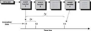
Figure 11.15: Unbounded soft-timer handler invocation.
Event handler 1 is invoked at t1 when the timeout has just expired. Similarly, event handler n is invoked at tn when the previous ( n -1) event handlers have finished execution. The interval x and y is non-deterministic because the length of execution of each handler is unknown. These intervals are also unbounded.
Ideally, the timer facility could guarantee an upper bound; for example, regardless of the number of timers already installed in the system, event handler n is invoked no later than 200ms from the actual expiration time.
This problem is difficult, and the solution is application specific.
11.6.2 Hierarchical Timing Wheels
The timer overflow problem presented in the last section can be solved using the hierarchical timing wheel approach.
The soft-timer facility needs to accommodate timer events spanning a range of values. This range can be very large. For example accommodating timers ranging from 100ms to 5 minutes requires a timing wheel with 3,000 (5 × 60 × 10) entries. Because the timer facility needs to have a granularity of at least 100ms and there is a single array representing the timing wheel,
10 × 100ms = 1 sec
10 entries/sec
60 sec = 1 minute
60 × 10 entries / min
therefore:
5 × 60 × 10 = total number of entries needed for the timing wheel with a granularity of 100ms.
A hierarchical timing wheel is similar to a digital clock. Instead of having a single timing wheel, multiple timing wheels are organized in a hierarchical order. Each timing wheel in the hierarchy set has a different granularity. A clock dial is associated with each timing wheel. The clock dial turns by one unit when the clock dial at the lower level of the hierarchy wraps around. Using a hierarchical timing wheel requires only 75 (10 + 60 + 5) entries to allow for timeouts with 100ms resolution and duration of up to 5 minutes.
With a hierarchical timing wheels, there are multiple arrays, therefore
10 × 100ms = 1 sec
10 entries/sec
the 1st array (leftmost array as shown in Figure 11.16)
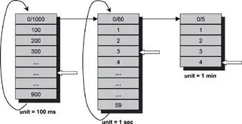
Figure 11.16: A hierarchical timing wheel.
60 sec = 1 minute
60 entries / min
the 2nd array (middle array shown in Figure 11.16)
5 entries for 5 minutes
3rd array
therefore:
5 + 60 + 10 = total number of entries needed for the hierarchal timing wheels.
The reduction in space allows for the construction of higher precision timer facilities with a large range of timeout values. Figure 11.16 depicts this concept.
For example, it is possible to install timeouts of 2 minutes, 4 seconds, and 300 milliseconds. The timeout handler is installed at the 2-minute slot first. The timeout handler determines that there are still 4.3 seconds to go when the 2 minutes is up. The handler installs itself at the 4-second timeout slot. Again, when 4 seconds have elapsed, the same handler determines that 300 milliseconds are left before expiring the timer. Finally, the handler is reinstalled at the 300-millisecond timeout slot. The real required work is performed by the handler when the last 300ms expire.
11.7 Soft Timers and Timer Related Operations
Many RTOSs provide a set of timer-related operations for external software components and applications through API sets. These common operations can be cataloged into these groups:
· group 1- provides low-level hardware related operations,
· group 2- provides soft-timer-related services, and
· group 3- provides access either to the storage of the real-time clock or to the system clock.
Not all of the operations in each of these three groups, however, are offered by all RTOSs, and some RTOSs provides additional operations not mentioned here.
The first group of operations is developed and provided by the BSP developers. The group is considered low-level system operations. Each operation in the group is given a fictitious function name for this discussion. Actual function names are implementation dependent.
Table 11.1: Group 1 Operations.
| Typical Operations | Description |
|---|---|
| sys_timer_enable | Enables the system timer chip interrupts. As soon as this operation is invoked, the timer interrupts occur at the preprogrammed frequency, assuming that the timer chip has been properly initialized with the desired values. Only after this operation is complete can kernel task scheduling take place. |
| sys_timer_disable | Disables the system timer chip interrupts. After this operation is complete, the kernel scheduler is no longer in effect. Other system-offered services based on time ticks are disabled by this operation as well. |
| sys_timer_connect | Installs the system timer interrupt service routine into the system exception vector table. The new timer ISR is invoked automatically on the next timer interrupt. The installed function is either part of the BSP or the kernel code and represents the 'timer ISR' depicted in Figure 11.3, page 172 . |
| Input Parameters:1. New timer interrupt service routine | |
| sys_timer_getrate | Returns the system clock rate as the number of ticks per second that the timer chip is programmed to generate. |
| Output Parameter:1. Ticks per second | |
| sys_timer_setrate | Sets the system clock rate as the number of ticks per second the timer chip generates. Internally, this operation reprograms the PIT to obtain the desired frequency. |
| Input Parameters:1. Ticks per second | |
| sys_timer_getticks | Returns the elapsed timer ticks since system power up. This figure is the total number of elapsed timer ticks since the system was first powered on. |
| Output Parameters:1. Total number of elapsed timer ticks |
The second group of timer-related operations includes the core timer operations that are heavily used by both the system modules and applications. Either an independent timer-handling facility or a built-in one that is part of the kernel offers these operations. Each operation in the group is given a fictitious function name for this discussion. Actual function names are implementation dependent.
The timer_create and timer_start operations allow the caller to start a timer that expires some time in the future. The caller-supplied function is invoked at the time of expiration, which is specified as a time relative with respect to when the timer_start operation is invoked. Through these timer operations, applications can install soft timers for various purposes. For example, the TCP protocol layer can install retransmission timers, the IP protocol layer can install packet-reassembly discard timers, and a device driver can poll an I/O device for input at predefined intervals.
Table 11.2: Group 2 Operations.
| Typical Operations | Description |
|---|---|
| timer_create | Creates a timer. This operation allocates a soft-timer structure. Any software module intending to install a soft timer must first create a timer structure. The timer structure contains control information that allows the timer-handling facility to update and expire soft timers. A timer created by this operation refers to an entry in the soft-timers array depicted in Figure 11.3. |
| Input Parameter:Expiration time. User function to be called at the timer expiration | |
| Output Parameter:An ID identifying the newly created timer structure | |
| Note:This timer structure is implementation dependent. The returned timer ID is also implementation dependent. | |
| timer_delete | Deletes a timer. This operation deletes a previously created soft timer, freeing the memory occupied by the timer structure. |
| Input Parameter:1. An ID identifying a previously created timer structure | |
| Note:This timer ID is implementation dependent. | |
| timer_start | Starts a timer. This operation installs a previously created soft timer into the timer-handling facility. The timer begins running at the completion of this operation. |
| Input Parameter:1. An ID identifying a previously created timer structure | |
| timer_cancel | Cancels a currently running timer. This operation cancels a timer by removing the currently running timer from the timer-handling facility. |
| Input Parameter:1. An ID identifying a previously created timer structure |
The third group is mainly used by user-level applications. The operations in this group interact either with the system clock or with the real-time clock. A system utility library offers these operations. Each operation in the group is given a fictitious function name for this discussion. Actual function names are implementation dependent.
Читать дальшеИнтервал:
Закладка:
Похожие книги на «Real-Time Concepts for Embedded Systems»
Представляем Вашему вниманию похожие книги на «Real-Time Concepts for Embedded Systems» списком для выбора. Мы отобрали схожую по названию и смыслу литературу в надежде предоставить читателям больше вариантов отыскать новые, интересные, ещё непрочитанные произведения.


Обсуждение, отзывы о книге «Real-Time Concepts for Embedded Systems» и просто собственные мнения читателей. Оставьте ваши комментарии, напишите, что Вы думаете о произведении, его смысле или главных героях. Укажите что конкретно понравилось, а что нет, и почему Вы так считаете.