Qing Li - Real-Time Concepts for Embedded Systems
Здесь есть возможность читать онлайн «Qing Li - Real-Time Concepts for Embedded Systems» весь текст электронной книги совершенно бесплатно (целиком полную версию без сокращений). В некоторых случаях можно слушать аудио, скачать через торрент в формате fb2 и присутствует краткое содержание. Город: San Francisco, Год выпуска: 2003, ISBN: 2003, Издательство: CMP books, Жанр: ОС и Сети, на английском языке. Описание произведения, (предисловие) а так же отзывы посетителей доступны на портале библиотеки ЛибКат.
- Название:Real-Time Concepts for Embedded Systems
- Автор:
- Издательство:CMP books
- Жанр:
- Год:2003
- Город:San Francisco
- ISBN:1-57820-124-1
- Рейтинг книги:4 / 5. Голосов: 1
-
Избранное:Добавить в избранное
- Отзывы:
-
Ваша оценка:
Real-Time Concepts for Embedded Systems: краткое содержание, описание и аннотация
Предлагаем к чтению аннотацию, описание, краткое содержание или предисловие (зависит от того, что написал сам автор книги «Real-Time Concepts for Embedded Systems»). Если вы не нашли необходимую информацию о книге — напишите в комментариях, мы постараемся отыскать её.
Delve into the details of real-time programming so you can develop a working knowledge of the common design patterns and program structures of real-time operating systems (RTOS). The objects and services that are a part of most RTOS kernels are described and real-time system design is explored in detail. You learn how to decompose an application into units and how to combine these units with other objects and services to create standard building blocks. A rich set of ready-to-use, embedded design “building blocks” is also supplied to accelerate your development efforts and increase your productivity.
Experienced developers new to embedded systems and engineering or computer science students will both appreciate the careful balance between theory, illustrations, and practical discussions. Hard-won insights and experiences shed new light on application development, common design problems, and solutions in the embedded space. Technical managers active in software design reviews of real-time embedded systems will find this a valuable reference to the design and implementation phases.
Qing Li is a senior architect at Wind River Systems, Inc., and the lead architect of the company’s embedded IPv6 products. Qing holds four patents pending in the embedded kernel and networking protocol design areas. His 12+ years in engineering include expertise as a principal engineer designing and developing protocol stacks and embedded applications for the telecommunications and networks arena. Qing was one of a four-member Silicon Valley startup that designed and developed proprietary algorithms and applications for embedded biometric devices in the security industry.
Caroline Yao has more than 15 years of high tech experience ranging from development, project and product management, product marketing, business development, and strategic alliances. She is co-inventor of a pending patent and recently served as the director of partner solutions for Wind River Systems, Inc. About the Authors
Real-Time Concepts for Embedded Systems — читать онлайн бесплатно полную книгу (весь текст) целиком
Ниже представлен текст книги, разбитый по страницам. Система сохранения места последней прочитанной страницы, позволяет с удобством читать онлайн бесплатно книгу «Real-Time Concepts for Embedded Systems», без необходимости каждый раз заново искать на чём Вы остановились. Поставьте закладку, и сможете в любой момент перейти на страницу, на которой закончили чтение.
Интервал:
Закладка:
Commonly, tables describing the mapping of a device's internal registers are available in the device hardware data book. The device registers appear at different offsets in this map. Sometimes the information is presented in the 'base + offset' format. This format indicates that the addresses in the map are relative, i.e., the offset must be added to the start address of the I/O space for port-mapped I/O or the offset must be added to the base address of the system memory space for memory-mapped I/O in order to access a particular register on the device.
The processor has to do some work in both of these I/O methods. Data transfer between the device and the system involves transferring data between the device and the processor register and then from the processor register to memory. The transfer speed might not meet the needs of high-speed I/O devices because of the additional data copy involved. Direct memory access (DMA) chips or controllers solve this problem by allowing the device to access the memory directly without involving the processor, as shown in Figure 12.4. The processor is used to set up the DMA controller before a data transfer operation begins, but the processor is bypassed during data transfer, regardless of whether it is a read or write operation. The transfer speed depends on the transfer speed of the I/O device, the speed of the memory device, and the speed of the DMA controller.
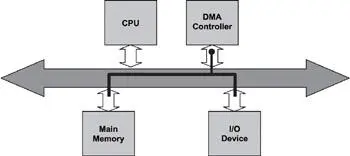
Figure 12.4: DMA I/O.
In essence, the DMA controller provides an alternative data path between the I/O device and the main memory. The processor sets up the transfer operation by specifying the source address, the destination memory address, and the length of the transfer to the DMA controller.
12.2.2 Character-Mode vs. Block-Mode Devices
I/O devices are classified as either character-mode devices or block-mode devices. The classification refers to how the device handles data transfer with the system.
Character-mode devices allow for unstructured data transfers. The data transfers typically take place in serial fashion, one byte at a time. Character-mode devices are usually simple devices, such as the serial interface or the keypad. The driver buffers the data in cases where the transfer rate from system to the device is faster than what the device can handle.
Block-mode devices transfer data one block at time, for example, 1,024 bytes per data transfer. The underlying hardware imposes the block size. Some structure must be imposed on the data or some transfer protocol enforced. Otherwise an error is likely to occur. Therefore, sometimes it is necessary for the block-mode device driver to perform additional work for each read or write operation, as shown in Figure 12.5.
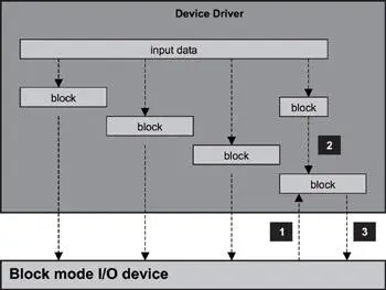
Figure 12.5: Servicing a write operation for a block-mode device.
As illustrated in Figure 12.5, when servicing a write operation with large amounts of data, the device driver must first divide the input data into multiple blocks, each with a device-specific block size. In this example, the input data is divided into four blocks, of which all but the last block is of the required block size. In practice, the last partition often is smaller than the normal device block size.
Each block is transferred to the device in separate write requests. The first three are straightforward write operations. The device driver must handle the last block differently from the first three because the last block has a different size. The method used to process this last block is device specific. In some cases, the driver pads the block to the required size. The example in Figure 12.5 is based on a hard-disk drive. In this case, the device driver first performs a read operation of the affected block and replaces the affected region of the block with the new data. The modified block is then written back.
Another strategy used by block-mode device drivers for small write operations is to accumulate the data in the driver cache and to perform the actual write after enough data has accumulated for a required block size. This technique also minimizes the number of device accesses. Some disadvantages occur with this approach. First, the device driver is more complex. For example, the block-mode device driver for a hard disk must know if the cached data can satisfy a read operation. The delayed write associated with caching can also cause data loss if a failure occurs and if the driver is shut down and unloaded ungracefully. Data caching in this case implies data copying that can result in lower I/O performance.
12.3 The I/O Subsystem
Each I/O device driver can provide a driver-specific set of I/O application programming interfaces to the applications. This arrangement requires each application to be aware of the nature of the underlying I/O device, including the restrictions imposed by the device. The API set is driver and implementation specific, which makes the applications using this API set difficult to port. To reduce this implementation-dependence, embedded systems often include an I/O subsystem.
The I/O subsystem defines a standard set of functions for I/O operations in order to hide device peculiarities from applications. All I/O device drivers conform to and support this function set because the goal is to provide uniform I/O to applications across a wide spectrum of I/O devices of varying types.
The following steps must take place to accomplish uniform I/O operations at the application-level.
1. The I/O subsystem defines the API set.
2. The device driver implements each function in the set.
3. The device driver exports the set of functions to the I/O subsystem.
4. The device driver does the work necessary to prepare the device for use. In addition, the driver sets up an association between the I/O subsystem API set and the corresponding device-specific I/O calls.
5. The device driver loads the device and makes this driver and device association known to the I/O subsystem. This action enables the I/O subsystem to present the illusion of an abstract or virtual instance of the device to applications.
This section discusses one approach to uniform I/O. This approach is general, and the goal is to offer insight into the I/O subsystem layer and its interaction with the application layer above and the device driver layer below. Another goal is to give the reader an opportunity to observe how the pieces are put together to provide uniform I/O capability in an embedded environment.
12.3.1 Standard I/O Functions
The I/O subsystem presented in the example in this section defines a set of functions as the standard I/O function set. Table 12.1 lists those functions that are considered part of the set in the general approach to uniform I/O. Again, remember that the example approach is used for illustration purposes in describing and discussing the I/O subsystem in general. The number of functions in the standard I/O API set, function names, and functionality of each is dependent on the embedded system and implementation. The next few sections put these functions into perspective.
Table 12.1: I/O functions.
| Function | Description |
|---|---|
| Create | Creates a virtual instance of an I/O device |
| Destroy | Deletes a virtual instance of an I/O device |
| Open | Prepares an I/O device for use. |
| Close | Communicates to the device that its services are no longer required, which typically initiates device-specific cleanup operations. |
| Read | Reads data from an I/O device |
| Write | Writes data into an I/O device |
| Ioctl | Issues control commands to the I/O device (I/O control) |
Note that all these functions operate on a so-called 'virtual instance' of the I/O device. In other words, these functions do not act directly on the I/O device, but rather on the driver, which passes the operations to the I/O device. When the open, read, write, and close operations are described, these operations should be understood as acting indirectly on an I/O device through the agency of a virtual instance.
Читать дальшеИнтервал:
Закладка:
Похожие книги на «Real-Time Concepts for Embedded Systems»
Представляем Вашему вниманию похожие книги на «Real-Time Concepts for Embedded Systems» списком для выбора. Мы отобрали схожую по названию и смыслу литературу в надежде предоставить читателям больше вариантов отыскать новые, интересные, ещё непрочитанные произведения.


Обсуждение, отзывы о книге «Real-Time Concepts for Embedded Systems» и просто собственные мнения читателей. Оставьте ваши комментарии, напишите, что Вы думаете о произведении, его смысле или главных героях. Укажите что конкретно понравилось, а что нет, и почему Вы так считаете.