Mohinder S. Grewal - Global Navigation Satellite Systems, Inertial Navigation, and Integration
Здесь есть возможность читать онлайн «Mohinder S. Grewal - Global Navigation Satellite Systems, Inertial Navigation, and Integration» — ознакомительный отрывок электронной книги совершенно бесплатно, а после прочтения отрывка купить полную версию. В некоторых случаях можно слушать аудио, скачать через торрент в формате fb2 и присутствует краткое содержание. Жанр: unrecognised, на английском языке. Описание произведения, (предисловие) а так же отзывы посетителей доступны на портале библиотеки ЛибКат.
- Название:Global Navigation Satellite Systems, Inertial Navigation, and Integration
- Автор:
- Жанр:
- Год:неизвестен
- ISBN:нет данных
- Рейтинг книги:4 / 5. Голосов: 1
-
Избранное:Добавить в избранное
- Отзывы:
-
Ваша оценка:
Global Navigation Satellite Systems, Inertial Navigation, and Integration: краткое содержание, описание и аннотация
Предлагаем к чтению аннотацию, описание, краткое содержание или предисловие (зависит от того, что написал сам автор книги «Global Navigation Satellite Systems, Inertial Navigation, and Integration»). Если вы не нашли необходимую информацию о книге — напишите в комментариях, мы постараемся отыскать её.
GNSSs including GPS, Glonass, Galileo, BeiDou, QZSS, and IRNSS/NAViC,
and MATLAB programs on square root information filtering (SRIF)
This book provides readers with solutions to real-world problems associated with global navigation satellite systems, inertial navigation, and integration. It presents readers with numerous detailed examples and practice problems, including GNSS-aided INS, modeling of gyros and accelerometers, and SBAS and GBAS. This revised fourth edition adds new material on GPS III and RAIM. It also provides updated information on low cost sensors such as MEMS, as well as GLONASS, Galileo, BeiDou, QZSS, and IRNSS/NAViC, and QZSS. Revisions also include added material on the more numerically stable square-root information filter (SRIF) with MATLAB programs and examples from GNSS system state filters such as ensemble time filter with square-root covariance filter (SRCF) of Bierman and Thornton and SigmaRho filter.
Global Navigation Satellite Systems, Inertial Navigation, and Integration, 4th Edition Updates on the significant upgrades in existing GNSS systems, and on other systems currently under advanced development Expanded coverage of basic principles of antenna design, and practical antenna design solutions More information on basic principles of receiver design, and an update of the foundations for code and carrier acquisition and tracking within a GNSS receiver Examples demonstrating independence of Kalman filtering from probability density functions of error sources beyond their means and covariances New coverage of inertial navigation to cover recent technology developments and the mathematical models and methods used in its implementation Wider coverage of GNSS/INS integration, including derivation of a unified GNSS/INS integration model, its MATLAB implementations, and performance evaluation under simulated dynamic conditions
is intended for people who need a working knowledge of Global Navigation Satellite Systems (GNSS), Inertial Navigation Systems (INS), and the Kalman filtering models and methods used in their integration.
Global Navigation Satellite Systems, Inertial Navigation, and Integration — читать онлайн ознакомительный отрывок
Ниже представлен текст книги, разбитый по страницам. Система сохранения места последней прочитанной страницы, позволяет с удобством читать онлайн бесплатно книгу «Global Navigation Satellite Systems, Inertial Navigation, and Integration», без необходимости каждый раз заново искать на чём Вы остановились. Поставьте закладку, и сможете в любой момент перейти на страницу, на которой закончили чтение.
Интервал:
Закладка:
1.2.4.1 BeiDou Satellites
BeiDou will consist of 27 MEO satellites, including 5 geostationary Earth orbit (GEO) satellites and 3 inclined geosynchronous orbit (IGSO) satellites. The GEO and IGSO satellites will be at longitudes to support the China and the surround areas of Southeast Asia.
1.2.4.2 Frequency
The BDS‐2 and BDS‐3 operate on various frequencies in the L1 (BDS‐3 B1C signal at 1575.42 MHz), E6 (BDS B3I signal at 1268.5 MHz), E5 (BDS‐2 and BDS‐3 at 1207.14 MHz; and BDS‐3 (B2a) at 1176.45 MHz). These signals use various navigation data formats from the BDS MEO, GEO, or IGSO satellites to support global and regional civil services. Details of this section are given in Chapter 4.
1.2.5 Regional Satellite Systems
There are several regional satellite systems that provide regional navigation and/or augmentation service.
1.2.5.1 QZSS
Quasi‐Zenith Satellite System (QZSS) is satellite‐based navigation system being developed by the Japanese government. QZSS has a constellation of four IGSO satellites that provide navigation and augmentation to GPS over Japan and Southeast Asia. The system transmits GPS‐type signals: L1 (L1 C/A and L1C), L2C, and L5, as well as, augmentation signals to support submeter and centimeter level services. Details of this section are given in Chapter 4.
1.2.5.2 NAVIC
The Indian Regional Navigation Satellite Systems, operationally known as NAVIC, is a regional satellite navigation system developed by the Indian Space Research Organization (ISRO). NAVIC constellation consists of eight satellites operation in GEO‐ and IGSO‐type orbits, where satellites transmit navigation signal in the L5 and S‐band. Details of this section are given in Chapter 4.
1.3 Inertial Navigation Overview
The following is a more‐or‐less heuristic overview of inertial navigation technology. Chapter 3 has the essential technical details about hardware and software used for inertial navigation, and Chapter 11 is about analytical methods for statistical characterization of navigation performance.
1.3.1 History
Although the theoretical foundations for inertial navigation have been around since the time of Isaac Newton (1643–1727), the technology for reducing it to practice would not become available until the twentieth century. This history can be found in the accounts by Draper [22], Gibson [23], Hellman [24], Mackenzie [2], Mueller [18], Wagner [25], and Wrigley [26]. For an account of the related computer hardware and software developments through that period, see McMurran [27].
1.3.1.1 Theoretical Foundations
It has been called “Newtonian navigation” [28] because its theoretical foundations have been known since the time of Newton. 2
Given the position x( t 0) and velocity v( t 0) of a vehicle at time t 0, and its acceleration a( s ) for times s > t 0, then its velocity v( t ) and position x( t ) for all time t > t 0can be defined as
(1.1) 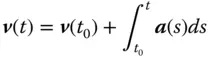
(1.2) 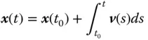
It follows that given the initial position x( t 0) and velocity v( t 0) of a vehicle or vessel, its subsequent position depends only on its subsequent accelerations. If these accelerations could be measured and integrated, this would provide a navigation solution.
Indications that this can be done can be found in nature:
1 Halters are an extra set of modified wings on some flying insects. During flight, these function as Coriolis vibratory gyroscopes (CVGs) to provide rotation rate feedback in attitude control. Their function was not known for a long time because they are too tiny to observe.
2 Vestibular systems include ensembles of gyroscopes (semicircular canals) and accelerometers (saccule and utricle) located in the bony mass behind each of your ears. Each of these is a complete 3D inertial measurement unit (IMU), used primarily to aid your vision system during rotations of the head but also useful for short‐term navigation in total darkness. These have been evolving since the time your ancestors were fish [29].
The development of man‐made solutions for inertial navigation came to have the same essential parts, except that they are not biological (yet).
1.3.1.2 Development Challenges: Then and Now
The technology of Newton's time was not adequate for practical implementation. What was missing included the following:
1 Methods for measuring three components of the acceleration vector a(t) in Eq. (1.1)with sufficient accuracy for the navigation problem.
2 Methods for maintaining the representation of vectors a(t) and v(t) in a common inertial coordinate frame for integration.
3 Methods for integrating a(t) and v(t) in real time (i.e. fast enough for the demands of the application).
4 Methods for initializing v(t) and x(t) in the common inertial coordinate frame.
5 Applications to justify the investments in technology required for developing the necessary solutions. It could not be justified for transportation at the pace of a sailing ship or a horse, but it could (and would) be justified by the military activities of World War II and the Cold War.
These challenges for inertial navigation system (INS) development were met and overcome during the great arms races of the mid‐to‐late twentieth century, the same time period that gave us GNSS. Like GNSS, INS technology first evolved for military applications and then became available for consumer applications as well. Today, the same concerns that have given us chip‐level GNSS receivers are giving us chip‐level inertial navigation technology. Chapter 3 describes the principles behind modern‐day inertial sensors, often using macro‐scale sensor models to illustrate what may be less obvious at the micro‐scale. The following subsections provide a more heuristic overview.
1.3.2 Development Results
1.3.2.1 Inertial Sensors
Rotation sensors are used in INSs for keeping track of the directions of the sensitive (input) axes of the acceleration sensors – so that sensed accelerations can be integrated in a fixed coordinate frame. Sensors for measuring rotation or rotation rates are collectively called gyroscopes , a term coined by Jean Bernard Léon Foucault (1819–1868). Foucault measured the rotation rate of Earth using two types of gyroscopes:
1 What is now called a momentum wheel gyroscope (MWG), which – if no torques are applied – tends to keep its spin axis in an inertially fixed direction while Earth rotates under it.
2 The Foucault pendulum, which might now be called a vibrating Coriolis gyroscope (vibrating at about 0.06 Hz). It depends on sinusoidal motion of a proof mass and the Coriolis 3 effect, an important design principle for miniature gyroscopes, as well.
Some of the physical phenomena used in the design of gyroscopes are listed in Table 1.1. Further explanation of the terminology is provided in Chapter 3.
Table 1.1A sampling of inertial sensor types.
| What it measures | Sensor types | Physical phenomena | Implementation methods |
| Rotation (gyroscope) | Momentum wheel gyroscope (MWG) | Conservation of angular momentum | Angle displacement |
| Torque rebalance | |||
| Coriolis vibratory gyroscope (CVG) | Coriolis effect and vibration | Balanced (tuning fork) | |
| Wine glass resonance | |||
| Optical gyroscope | Sagnac effect | Fiber optic gyroscope (FOG) | |
| Ring laser gyroscope (RLG) | |||
| Acceleration (accelerometer) | Mass spring (fish example) | Stress in support | Piezoresistive |
| Piezoelectric | |||
| Surface acoustic wave | |||
| Vibrating wire in tension | |||
| Electromagnetic | Induction | Drag cup | |
| Electromagnetic force | Force rebalance | ||
| Pendulous integrating gyroscopic accelerometer (PIGA) | Gyroscopic precession | Angular displacement | |
| Torque rebalance | |||
| Electrostatic | Electrostatic force | Force rebalance |
What we call acceleration sensors or accelerometers actually measure specific force , equal to the physical force applied to a mass divided by the mass, solving f = ma for a , given f (the sensor input) and m (a known constant). Accelerometers do not measure gravitational acceleration , but can measure the force applied to counter gravity. A spring scale used in a fish market for measuring the mass m of a fish, for example, is actually measuring the spring force f applied to the fish by the spring for countering gravity, solving f = ma for m , given f (spring strain, proportional to force) and a (local gravity being countered).
Читать дальшеИнтервал:
Закладка:
Похожие книги на «Global Navigation Satellite Systems, Inertial Navigation, and Integration»
Представляем Вашему вниманию похожие книги на «Global Navigation Satellite Systems, Inertial Navigation, and Integration» списком для выбора. Мы отобрали схожую по названию и смыслу литературу в надежде предоставить читателям больше вариантов отыскать новые, интересные, ещё непрочитанные произведения.


Обсуждение, отзывы о книге «Global Navigation Satellite Systems, Inertial Navigation, and Integration» и просто собственные мнения читателей. Оставьте ваши комментарии, напишите, что Вы думаете о произведении, его смысле или главных героях. Укажите что конкретно понравилось, а что нет, и почему Вы так считаете.