1 ...6 7 8 10 11 12 ...37 Inspection of the drawing of the arrangement of the ions in a crystal of caesium chloride, CsCl, in Figure 3.17 shows that the lattice is an array of points such that a = b = c , α = β = γ = 90°, so that the unit cell is a cube. There is one caesium ion and one chlorine ion associated with each lattice point. If we take the origin at the centre of a caesium ion, then there is one caesium ion in the unit cell with coordinates (0, 0, 0) and one chlorine ion with coordinates  . A projection along the z ‐axis is shown in Figure 1.3. It must be remembered that the caesium ions at the corners of the unit cell project on top of one another; thus, ions at elevations 0 and 1 are superimposed, as indicated in Figure 1.3. Since translational symmetry dictates that if there is an ion at ( x , y , 0), there must be an ion with exactly the same environment at ( x , y , 1), the ions at elevation 1 along the z ‐axis can be omitted by convention. It is also standard practice when drawing projections of crystal structures not to indicate the elevations of atoms or ions if they are 0.
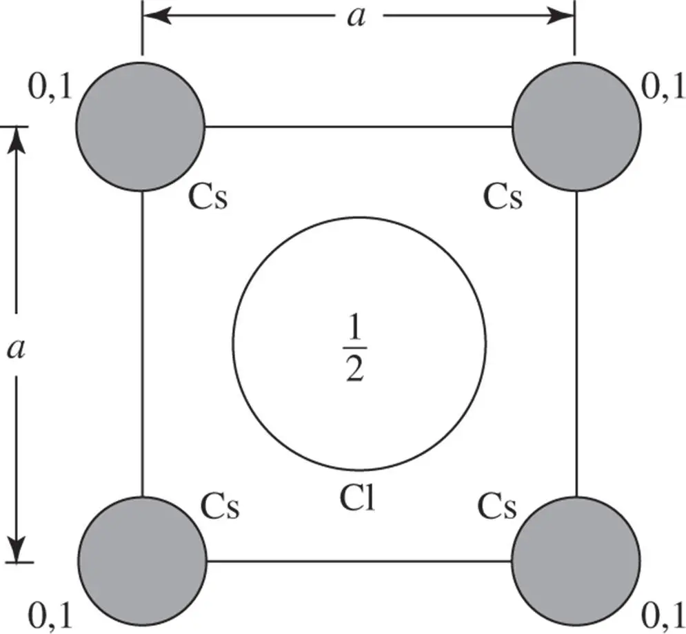
Figure 1.3The numbers give the elevations of the centres of the atoms, along the z ‐axis, taking the lattice parameter c as the unit of length
It is apparent from this drawing of the crystal structure of caesium chloride that the coordination number for each caesium ion and each chlorine ion is eight, each ion having eight of the other kind of ion as neighbours. The separation of these nearest neighbours, d , is easily seen to be given by:
(1.1) 
since a = b = c .
The number of units of the formula CsCl per unit cell is clearly 1.
1.2 Lattice Planes and Directions
A rectangular mesh of a hypothetical two‐dimensional crystal with mesh parameters a and b of very different magnitude is shown in Figure 1.4. Note that the parallel mesh lines OB, O′B′, O″B″, and so on all form part of a set and that the spacing of all lines in the set is quite regular; this is similar for the set of lines parallel to AB: A′B′, A″B″ and so on. The spacing of each of these sets is determined only by aand b(and the angle between aand b,which in this example is 90°). Also, the angle between these two sets depends only on the ratio of a to b, where a and b are the magnitudes of aand b, respectively. If external faces of the crystal formed parallel to O″B and to AB, the angle between these faces would be uniquely related to the ratio a : b . Furthermore, this angle would be independent of how large these faces were (see Figure 1.5). This was recognized by early crystallographers, who deduced the existence of the lattice structure of crystals from the observation of the constancy of angles between corresponding faces. This law of constancy of angle states: In all crystals of the same substance the angle between corresponding faces has a constant value .
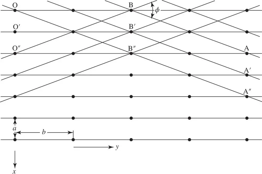
Figure 1.4A rectangular mesh of a hypothetical two‐dimensional crystal with mesh parameters a and b of very different magnitude
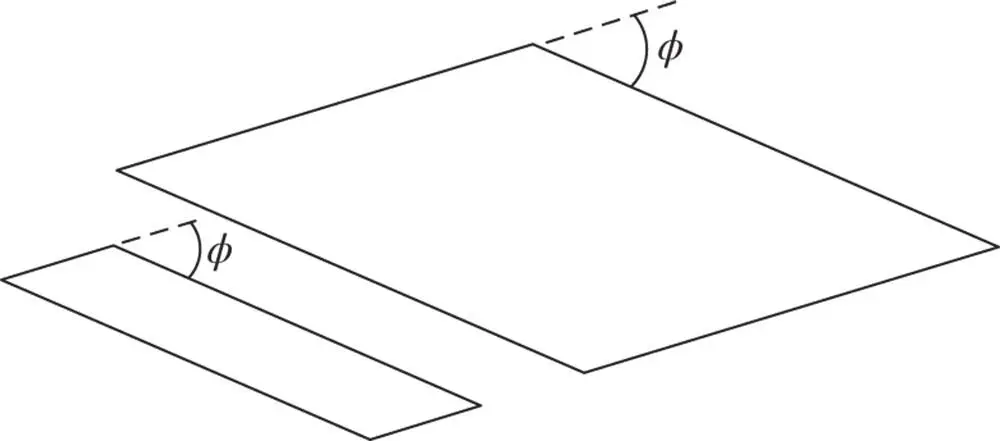
Figure 1.5Demonstration of the law of constancy of angles between faces of crystals: the angle φ between the faces is independent of the size of the faces
The analogy between lines in a mesh and planes in a crystal lattice is very close. Crystal faces form parallel to lattice planes and important lattice planes contain a high density of lattice points. Lattice planes form an infinite regularly spaced set which collectively passes through all points of the lattice. The spacing of the members of the set is determined only by the lattice parameters and axial angles, and the angles between various lattice planes are determined only by the axial angles and the ratios of the lattice parameters to one another.
Prior to establishing a methodology for designating a set of lattice planes, it is expedient to consider how directions in a crystal are specified. A direction is simply a line in the crystal. Select any two points on the line, say P and P′. Choose one as the origin, say P ( Figure 1.6). Write the vector rbetween the two points in terms of translations along the x ‐, y ‐ and z ‐axes so that:
(1.2) 
where a, band care vectors along the x ‐, y ‐ and z ‐axes, respectively, and have magnitudes equal to the lattice parameters ( Figure 1.6). The direction is then denoted as [ uvw ] – always cleared of fractions and reduced to its lowest terms. The triplet of numbers indicating a direction is always enclosed in square brackets. Some examples are given in Figure 1.7. Negative values of u , v and w are indicated in this figure by a bar over the appropriate index.
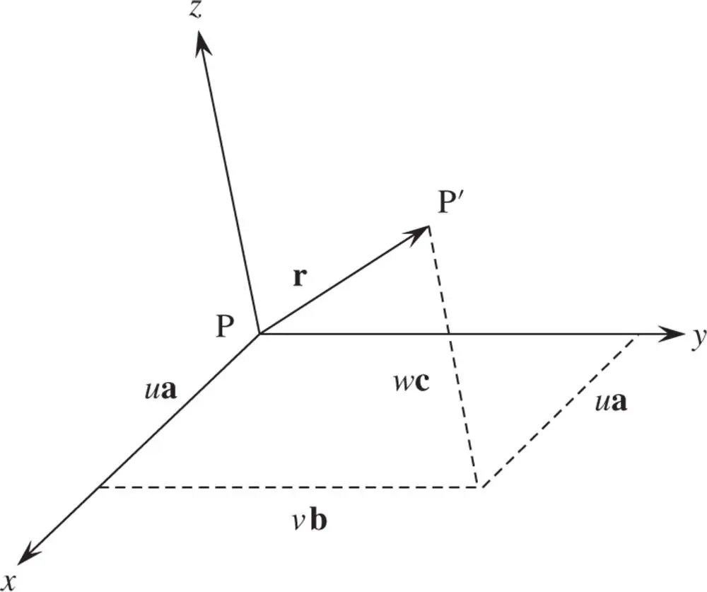
Figure 1.6A vector rwritten as the sum of translations along the x ‐, y ‐ and z ‐axes
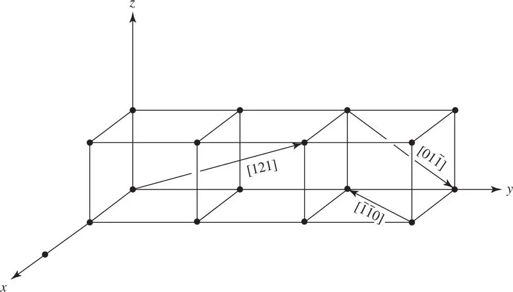
Figure 1.7Examples of various lattice vectors in a crystal
If u , v and w are integers and the origin P is chosen at a lattice point, then P′ is also a lattice point and the line PP′ produced is a row of lattice points. Such a line is called a rational line, just as a plane of lattice points is called a rational plane.
We designate a set of lattice planes as follows (see Figure 1.8). Let one member of the set meet the chosen axes, x , y , z at distances from the origin of A, B and C, respectively. We can choose the origin to be a lattice point. Vectors a, band cthen define the distances between adjacent lattice points along the x ‐, y ‐ and z ‐axes, respectively. The Miller 3indices ( hkl ) of the set of lattice planes are then defined in terms of the intercepts A, B and C so that the length OA = a / h , where a is the magnitude of a; likewise, OB = b / k and OC = c / l .
Читать дальше

 . A projection along the z ‐axis is shown in Figure 1.3. It must be remembered that the caesium ions at the corners of the unit cell project on top of one another; thus, ions at elevations 0 and 1 are superimposed, as indicated in Figure 1.3. Since translational symmetry dictates that if there is an ion at ( x , y , 0), there must be an ion with exactly the same environment at ( x , y , 1), the ions at elevation 1 along the z ‐axis can be omitted by convention. It is also standard practice when drawing projections of crystal structures not to indicate the elevations of atoms or ions if they are 0.


