Ben Piper - CCNP Enterprise Certification Study Guide - Implementing and Operating Cisco Enterprise Network Core Technologies
Здесь есть возможность читать онлайн «Ben Piper - CCNP Enterprise Certification Study Guide - Implementing and Operating Cisco Enterprise Network Core Technologies» — ознакомительный отрывок электронной книги совершенно бесплатно, а после прочтения отрывка купить полную версию. В некоторых случаях можно слушать аудио, скачать через торрент в формате fb2 и присутствует краткое содержание. Жанр: unrecognised, на английском языке. Описание произведения, (предисловие) а так же отзывы посетителей доступны на портале библиотеки ЛибКат.

- Название:CCNP Enterprise Certification Study Guide: Implementing and Operating Cisco Enterprise Network Core Technologies
- Автор:
- Жанр:
- Год:неизвестен
- ISBN:нет данных
- Рейтинг книги:4 / 5. Голосов: 1
-
Избранное:Добавить в избранное
- Отзывы:
-
Ваша оценка:
CCNP Enterprise Certification Study Guide: Implementing and Operating Cisco Enterprise Network Core Technologies: краткое содержание, описание и аннотация
Предлагаем к чтению аннотацию, описание, краткое содержание или предисловие (зависит от того, что написал сам автор книги «CCNP Enterprise Certification Study Guide: Implementing and Operating Cisco Enterprise Network Core Technologies»). Если вы не нашли необходимую информацию о книге — напишите в комментариях, мы постараемся отыскать её.
. This guide helps you develop practical knowledge and best practices for critical aspects of enterprise infrastructure so you can gain your CCNP Enterprise certification. If you’re hoping to attain a broader range of skills and a solid understanding of Cisco technology, this guide will also provide fundamental concepts for learning how to implement and operate Cisco enterprise network core technologies By focusing on real-world skills, each chapter prepares you with the knowledge you need to excel in your current role and beyond. It covers emerging and industry-specific topics, such as SD-WAN, network design, wireless, and automation. This practical guide also includes lessons on:
● Automation
● Network assurance
● Security
● Enterprise infrastructure
● Dual-stack architecture
● Virtualization
In addition to helping you gain enterprise knowledge, this study guidecan lead you toward your Cisco specialist certification.
When you purchase this guide, you get access to the information you need to prepare yourself for advances in technology and new applications, as well as online study tools such as:
● Bonus practice exams
● Pre-made flashcards
● Glossary of key terms
● Specific focus areas
Expand your skillset and take your career to the next level with
CCNP Enterprise Certification Study Guide: Implementing and Operating Cisco Enterprise Network Core Technologies — читать онлайн ознакомительный отрывок
Ниже представлен текст книги, разбитый по страницам. Система сохранения места последней прочитанной страницы, позволяет с удобством читать онлайн бесплатно книгу «CCNP Enterprise Certification Study Guide: Implementing and Operating Cisco Enterprise Network Core Technologies», без необходимости каждый раз заново искать на чём Вы остановились. Поставьте закладку, и сможете в любой момент перейти на страницу, на которой закончили чтение.
Интервал:
Закладка:
With the exception of the Physical layer, the layers of the OSI model are purely imaginary. Just as a filesystem is a software abstraction that hides the details of physical storage, the layers of the OSI model are just collections of software functions that hide the details of the network from applications and users. You can't see a filesystem with your eyes in the same way that you can see a hard drive, and you can't see the Data Link layer in the same way that you can see a switch. Layers are software abstractions and nothing more.
Figure 1.1illustrates the concept of how layering might work using the Transmission Control Protocol (TCP) and Internet Protocol (IP), which are both included in the kernels of modern operating systems (Linux, Unix, and Windows). Keep in mind that the only real objects in this figure are the host and the physical network interface.
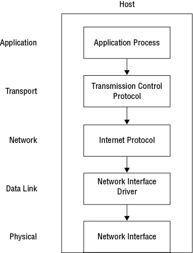
Figure 1.1 How layers abstract the network from an application
 You may see some striking similarities between the layers in Figure 1.1and the so-called TCP/IP or Internet protocol suite model. It and the OSI model are often juxtaposed as competing models. The fact is that the TCP/IP model is just a specific implementation of the OSI model based on the TCP/IP protocol suite.
In this high-level example, when an application needs to send data it places the data in what the OSI model generically calls an application protocol data unit (PDU). The specifics of the application PDU aren't important and, with the exception of firewalls that do deep packet inspection, are opaque to the network. The application passes its PDU to a protocol in the layer directly below, as shown in Figure 1.2. The protocol generates a new PDU and tacks the application PDU onto the end of it—a process called encapsulation . It then passes this new PDU down to a protocol at the next lower layer, and so on. What ends up on the wire is a giant PDU that contains several smaller PDUs from the protocols operating at the higher layers. Later in the chapter we'll walk through a detailed example of how encapsulation works, but first, we need to talk about what happens at each of these lower layers.
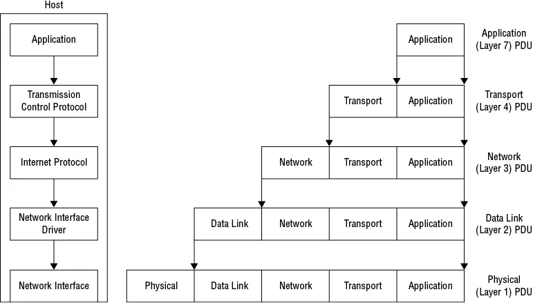
Figure 1.2 At each layer, data is encapsulated in a PDU and passed down to the next lower layer.
The Lower Layers: Physical, Data Link, Network, and Transport
The purpose of a network is to allow applications running on different hosts to communicate with one another. Robert Metcalfe, one of the inventors of the original Ethernet, said it succinctly in 1972: “Networking is interprocess communication.” Thus, at a minimum, a network needs to perform three basic functions:
Layer 1: Physical Connectivity between NodesA node can be a workstation, server, router, switch, firewall, or any network-connected device that has a processor and memory.
Layer 2: Node-to-Node Data TransferData transfer between two nodes physically connected to a shared medium.
Layer 3: Forwarding/RoutingData transfer between any two nodes, regardless of whether they're physically connected to the same medium.
The OSI model sorts these three functions along with many others into the first four layers of the OSI model, as shown in Table 1.2. Not all protocols that operate in a given layer implement all the functions listed for that layer.
Table 1.2 Networking functions provided by each layer
| Function | 1 Physical | 2 Data Link | 3 Network | 4 Transport |
| Transmission of bitstreams over physical media | X | |||
| Enabling/disabling physical network interface | X | |||
| Node-to-node data transfer over a shared medium | X | |||
| Forwarding/routing | X | X | ||
| Error control | X | X | X | |
| Flow control | X | X | X | |
| Multiplexing/splitting | X | X | X | |
| Ordering | X | X | X | |
| Fragmentation/reassembly | X | X |
The OSI replicates some functions in most layers, blurring the distinction among them. It becomes apparent that what distinguishes the layers isn't what they do but what they don't do. Higher layers lack functionality provided by lower layers, something you'd expect given the hierarchical structure of layers. One layer whose functions differ starkly from the others is the Physical layer.
Layer 1: The Physical Layer
The main function of the Physical layer is to convert bits to electromagnetic energy such as light, electrical current, or radio waves, and transmit them over some medium such as fiber-optic or copper cables or the airwaves. Whereas the functions of the other layers are performed in software, this particular function is performed by a node's physical network interface.
A challenge of using electromagnetic energy to send bits is that the physical media can carry only one bitstream at a time. In the early days of networking, two nodes would be connected via a pair of wires. If both simultaneously sent a signal, their signals would interfere with each other and create a collision. Hence, both nodes were in the same collision domain. To avoid this, the nodes had to use half-duplex communication wherein only one node could transmit at a time. Half-duplex wired communication may seem an irrelevant relic from the past, but as you'll learn in a moment, during its heyday half-duplex communication had an unfortunate impact on the Ethernet standards that still haunts us to this day. Broadcast storms and the infamous Spanning Tree Protocols (STPs) can be traced back to the early use of half-duplex communication.
Today, full-duplex communication is the norm in wired networks and something we take for granted. All that's needed for full-duplex communication is for the physical interface to separate the transmit and receive functions. Twisted-pair copper cabling, for example, does this by using two pairs of wires: one pair for transmitting and another pair for receiving. Likewise, fiber-optic cables have separate strands for transmitting and receiving. Wavelength-division multiplexing achieves full-duplex communication on a single fiber strand by using one light frequency for transmitting and another for receiving.
Layer 2: The Data Link Layer
The primary function of the Data Link layer is to facilitate data transfer between two (and only two) nodes that are connected to a shared medium. Some physical media can support only two nodes, as is the case with a crossover cable or point-to-point serial link. Other media, such as wireless, can support more than two nodes.
When only two nodes share the same media, data transfer is easy. As long as both nodes are aware of the point-to-point nature of the link, one node can send the data, and the other node receives it, knowing that it's the intended recipient. The Point-to-Point Protocol (PPP) and High-level Data Link Control (HDLC) are two common layer 2 protocols used on T1 serial links.
Читать дальшеИнтервал:
Закладка:
Похожие книги на «CCNP Enterprise Certification Study Guide: Implementing and Operating Cisco Enterprise Network Core Technologies»
Представляем Вашему вниманию похожие книги на «CCNP Enterprise Certification Study Guide: Implementing and Operating Cisco Enterprise Network Core Technologies» списком для выбора. Мы отобрали схожую по названию и смыслу литературу в надежде предоставить читателям больше вариантов отыскать новые, интересные, ещё непрочитанные произведения.


Обсуждение, отзывы о книге «CCNP Enterprise Certification Study Guide: Implementing and Operating Cisco Enterprise Network Core Technologies» и просто собственные мнения читателей. Оставьте ваши комментарии, напишите, что Вы думаете о произведении, его смысле или главных героях. Укажите что конкретно понравилось, а что нет, и почему Вы так считаете.