Saeid Sanei - Body Sensor Networking, Design and Algorithms
Здесь есть возможность читать онлайн «Saeid Sanei - Body Sensor Networking, Design and Algorithms» — ознакомительный отрывок электронной книги совершенно бесплатно, а после прочтения отрывка купить полную версию. В некоторых случаях можно слушать аудио, скачать через торрент в формате fb2 и присутствует краткое содержание. Жанр: unrecognised, на английском языке. Описание произведения, (предисловие) а так же отзывы посетителей доступны на портале библиотеки ЛибКат.
- Название:Body Sensor Networking, Design and Algorithms
- Автор:
- Жанр:
- Год:неизвестен
- ISBN:нет данных
- Рейтинг книги:5 / 5. Голосов: 1
-
Избранное:Добавить в избранное
- Отзывы:
-
Ваша оценка:
Body Sensor Networking, Design and Algorithms: краткое содержание, описание и аннотация
Предлагаем к чтению аннотацию, описание, краткое содержание или предисловие (зависит от того, что написал сам автор книги «Body Sensor Networking, Design and Algorithms»). Если вы не нашли необходимую информацию о книге — напишите в комментариях, мы постараемся отыскать её.
, professionals in the field of Biomedical Engineering and e-health get an in-depth look at advancements, changes, and developments. When it comes to advances in the industry, the text looks at cooperative networks, noninvasive and implantable sensor microelectronics, wireless sensor networks, platforms, and optimization—to name a few.
Each chapter provides essential information needed to understand the current landscape of technology and mechanical developments. It covers subjects including Physiological Sensors, Sleep Stage Classification, Contactless Monitoring, and much more.
Among the many topics covered, the text also includes additions such as:
● Over 120 figures, charts, and tables to assist with the understanding of complex topics
● Design examples and detailed experimental works
● A companion website featuring MATLAB and selected data sets
Additionally, readers will learn about wearable and implantable devices, invasive and noninvasive monitoring, biocompatibility, and the tools and platforms for long-term, low-power deployment of wireless communications. It’s an essential resource for understanding the applications and practical implementation of BSN when it comes to elderly care, how to manage patients with chronic illnesses and diseases, and use cases for rehabilitation.
Body Sensor Networking, Design and Algorithms — читать онлайн ознакомительный отрывок
Ниже представлен текст книги, разбитый по страницам. Система сохранения места последней прочитанной страницы, позволяет с удобством читать онлайн бесплатно книгу «Body Sensor Networking, Design and Algorithms», без необходимости каждый раз заново искать на чём Вы остановились. Поставьте закладку, и сможете в любой момент перейти на страницу, на которой закончили чтение.
Интервал:
Закладка:
Currently, most work into the simulation of accelerometers deals with verifying a design at the semiconductor fabrication level.
There are three major challenges in the design and use of accelerometers. The first is the effect of drift or change in the internal mechanical or electrical properties, which can manifest itself as a bias or an offset in readings. The second is noise from amplified microscopic mechanical motions, which needs to be reduced if not eliminated. The third is the effect of gravity, which is ever present. While this is strictly not a defect, we have to consider that the gravitational force vector is projected and superimposed along the axes of sensitivity of the accelerometer. Thus, the movements along these axes experience a confounding gravitational effect. Furthermore, with movements at frequencies beyond 10 kHz, the internal mechanical parts of an accelerometer move nonlinearly, resulting in dynamic errors.
3.2.1.1 How Accelerometers Operate
A capacitive accelerometer measures acceleration by changes in the internal capacitance of the device. These devices are typically fabricated using MEMS technology on microstructures built into polysilicon. Some microstructures are fixed and some are movable, suspended from fixed points. By impressing a voltage between them, a capacitive effect arises from the electronic charge stored in these structures which is proportional to the area and the physical distances between these structures. External physical movements cause the distances between the microstructures to change, which in turn results in changes to the capacitance. These variations eventually cause changes to the voltage.
Acceleration has two main components: the first being the inertial acceleration that is corresponding to the changes in speed, resulting from rotation or translation, or both. The second component consists of gravitational acceleration arising from the microstructures being deflected in proportion to their static orientation to the gravitational field. Removing the confounding effect of this kind of acceleration [23] can be cumbersome.
In the simplified diagram presented in Figure 3.2the parameter changes corresponding to acceleration happen between a proof mass to which some plates are attached. The proof mass is suspended from the body or frame of the accelerometer device and secured through anchor points. Another set of plates which are fixed to the frame and the changes in the distance between the two induce a change in the voltage between the plates. When the accelerometer frame moves, the inertia of the proof mass induces a reactionary force which is applied to the springs (often fabricated from polysilicon). These springs are affixed to the frame of the device at anchor points. The spring deformation is assumed to be linear so that the accelerometer obeys the familiar mass–spring–damper equation derived from Newton's and Hooke's Laws [24]:
(3.1) 
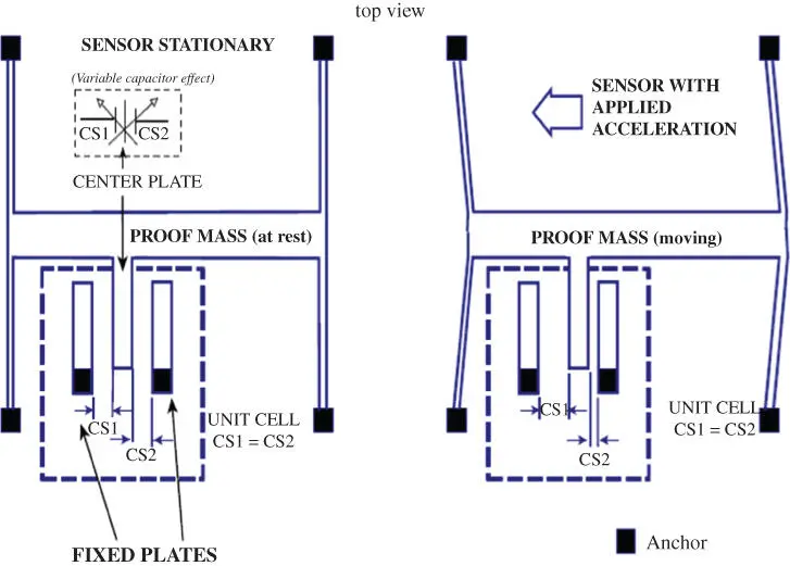
Figure 3.2 Top view of a simplified accelerometer sensor from ADXL50 [49] datasheet. Anchor points move with the device frame, while inertia of the proof mass causes the distance between fixed plates to vary, changing the capacitance [20].
Source: Courtesy of Jarchi, D., Pope, J., Lee, T.K.M., Tamjidi, L., Mirzaei, A. and Sanei, S.
where M is the mass of proof mass, Eand Dare the distances travelled by the proof mass with respect to the earth and to its anchors respectively, b is the damping factor, and k the spring constant. The differentiation is with respect to time t . In addition, there are electrostatic forces between the fixed and moving plates to be considered. In order to measure the speed of movement, consider the relative motion between the stationary plates and the moving proof mass which changes the capacitance between them.
However, to measure the acceleration, the transfer of charge is amplified electronically by mixing with a high-frequency signal using a double sideband suppressed carrier modulation technique. Finally, the amplitude-modulated signal is synchronously demodulated and amplified.
There are several ways to evaluate the movement resulting from the changes in capacitance. Early methods used closed loop feedback by impressing a voltage on the capacitor plates so the proof mass stays at its original position [25]. Changes in this voltage thus reflect the change in position. More recent methods are open loop, where the capacitance is obtained using switched-capacitor techniques.
Despite the widespread use of accelerometers, there are limitations of current devices which prevent them from being used in even more applications. A prime example is that of deriving the speed and distance moved by performing mathematical integration of the measured acceleration. In practice, the measurements drift and the integration causes accumulation of these errors rendering the readings useless. To overcome this, it is necessary to periodically recalibrate the accelerometer readings. One popular method is zero-velocity update point (ZUPT). Other schemes depend on the instances where an external event indicates an instantaneous null in the movement pattern, for example in between footsteps [25].
Another source of accelerometer disturbance is the noise arising from mechanical sources due to the proof mass being subjected to Brownian motion. Nevertheless, electronic sources themselves generate considerable noise. The conversion of minute capacitance changes to usable voltages requires high electronic gain and, with that, an increase in noise. A widely used method benefits from switched-capacitor techniques, and the oscillation frequency can be superimposed to the main signal, resulting in an aliasing effect. This may be worsened when using chopper amplification with synchronous demodulation, often applied to moderate the effect of drift.
3.2.1.2 Accelerometers in Practice
Accelerometers have gained even wider use by being part of consumer devices like smartphones and tablets. It is useful to differentiate between such installed units and those available as standalone units, where the accelerometer integrated circuit has settings for force sensitivity. The external components may filter part of the operating frequencies too. These units are small in size and consume little current but need to have proper packaging.
By way of contrast, in ready-to-use consumer devices, there is no control over how an accelerometer is mounted in its physical environment. This affects its operating conditions in terms of temperature, humidity, and electronic interference. In addition, inevitable smoothing of the measurements by means of digital filtering and processing may introduce further latencies. Nevertheless, in many situations, in order to achieve device independence [26], the accelerometer is treated as a ‘black box’, where the digital readout is assumed to be a measure of the acceleration. Then, the imperfections are treated statistically and data calibration would need to be employed for demanding applications. In spite of this, the use of accelerometers in consumer devices has proven to be adequate for many clinical purposes, mainly due to their compatibility with many computing systems and microcontrollers and also their flexibility in terms of price, size, and application as seen in various publications, such as [27]. In such applications the measurements are compared with gold standard equipment like motion capture cameras and accelerometers built in instruments designed for clinical use.
Читать дальшеИнтервал:
Закладка:
Похожие книги на «Body Sensor Networking, Design and Algorithms»
Представляем Вашему вниманию похожие книги на «Body Sensor Networking, Design and Algorithms» списком для выбора. Мы отобрали схожую по названию и смыслу литературу в надежде предоставить читателям больше вариантов отыскать новые, интересные, ещё непрочитанные произведения.


Обсуждение, отзывы о книге «Body Sensor Networking, Design and Algorithms» и просто собственные мнения читателей. Оставьте ваши комментарии, напишите, что Вы думаете о произведении, его смысле или главных героях. Укажите что конкретно понравилось, а что нет, и почему Вы так считаете.