Fig. 2-10 Actual and linearized friction characteristics.
TABLE 2-1 Drag Force and the Power Required
| Vehicle |
u = 50 km/h |
u = 100 km/h |
| C w= 0.3 |
f L= 62.06 N |
P = 0.86 kW |
f L= 248.2 N |
P = 6.9 kW |
| C w= 0.5 |
f L= 103.4 N |
P = 1.44 kW |
f L= 413.7 N |
P = 11.5 kW |
In Fig. 2-7, the shaft connecting the motor with the load was assumed to be of infinite stiffness, that is, the two were rigidly connected. In reality, any shaft will twist (flex) as it transmits torque from one end to the other. In Fig. 2-11, the torque T shaftavailable to be transmitted by the shaft is
(2-31) 
This torque at the load‐end overcomes the load torque and accelerates it,
(2-32) 

Fig. 2-11 Motor and load‐torque interaction with a rigid coupling.
The twisting or flexing of the shaft, in terms of the angles at the two ends, depends on the shaft torsional or the compliance coefficient K :
(2-33) 
where θ Mand θ Lare the angular rotations at the two ends of the shaft. If K is infinite, θ M= θ L. For a shaft of finite compliance, these two angles are not equal, and the shaft acts as a spring. This compliance in the presence of energy stored in the masses, and inertias of the system, can lead to resonance conditions at certain frequencies. This phenomenon is often termed torsional resonance. Such resonances should be avoided or kept low; otherwise they can lead to fatigue and failure of the mechanical components.
An analogy with electrical circuits can be very useful when analyzing mechanical systems. A commonly used analogy, though not a unique one, is to relate mechanical and electrical quantities, as shown in Table 2-2.
TABLE 2-2 Torque–Current Analogy
| Mechanical system |
Electrical system |
| Torque ( T ) |
Current ( i ) |
| Angular speed ( ω m) |
Voltage ( v ) |
| Angular displacement ( θ ) |
Flux linkage ( ψ ) |
| Moment of inertia ( J ) |
Capacitance ( C ) |
| Spring constant ( K ) |
1/Inductance (1/ L ) |
| Damping coefficient ( B ) |
1/Resistance (1/ R ) |
| Coupling ratio ( n M/ n L) |
Transformer ratio ( n L/ n M) |
The coupling ratio is discussed later in this chapter.
For the mechanical system shown in Fig. 2-11, Fig. 2-12a shows the electrical analogy, where each inertia is represented by a capacitor from its node to a reference (ground) node. In this circuit, we can write equations similar to Eqs. (2-31)through (2-33). Assuming that the shaft is of infinite stiffness, the inductance representing it becomes zero, and the resulting circuit is shown in Fig. 2-12b, where ω m= ω M= ω L. The two capacitors representing the two inertias can now be combined to result in a single equation similar to Eq. (2-23).
In an electric‐motor drive, similar to that shown in Fig. 2-7a, the combined inertia is J eq= 5 × 10 −3kg ⋅ m 2. The load torque opposing rotation is mainly due to friction and can be described as T L= 0.5 × 10 −3 ω L. Draw the electrical equivalent circuit and plot the electromagnetic torque required from the motor to bring the system linearly from rest to a speed of 100 rad/s in 4 s, and then to maintain that speed.
The electrical equivalent circuit is shown in Fig. 2-13a. The inertia is represented by a capacitor of 5 mF, and the friction by a resistance R = 1/(0.5 × 10 −3) = 2000 Ω . The linear acceleration is 100/4 = 25 rad/s 2, which in the equivalent electrical circuit corresponds to dv / dt = 25 V/s. Therefore, during the acceleration period, v ( t ) = 25 t . Thus, the capacitor current during the linear acceleration interval is
(2-34a) 
and the current through the resistor is
(2-34b) 
Therefore,
(2-34c) 
Beyond the acceleration stage, the electromagnetic torque is required only to overcome friction, which equals 50 × 10 −3Nm, as plotted in Fig. 2-13b.

Fig. 2-12 Electrical analogy: (a) shaft of finite stiffness and (b) shaft of infinite stiffness.
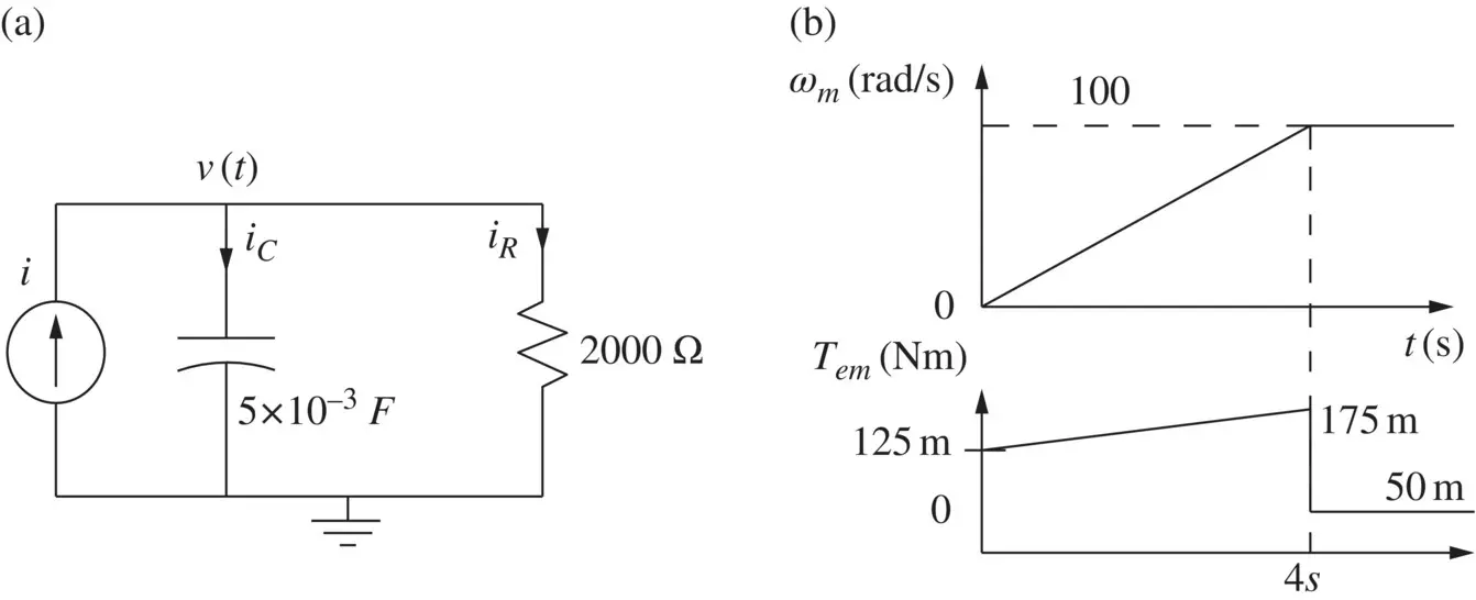
Fig. 2-13 (a) Electrical equivalent and (b) torque and speed variation.
Wherever possible, it is preferable to couple the load directly to the motor, to avoid the additional cost of the coupling mechanism and the associated power losses. In practice, coupling mechanisms are often used for the following reasons:
A rotary motor is driving a load which requires linear motion.
The motors are designed to operate at higher rotational speeds (to reduce their physical size) compared to the speeds required of the mechanical loads.
The axis of rotation needs to be changed.
There are various types of coupling mechanisms. For conversion between rotary and linear motions, it is possible to use conveyor belts (belt and pulley), rack‐and‐pinion, or a lead‐screw type of arrangement. For rotary‐to‐rotary motion, various types of gear mechanisms are employed.
The coupling mechanisms have the following disadvantages:
Additional power loss.
Introduction of nonlinearity due to a phenomenon called backlash.
Wear and tear.
2‐7‐1 Conversion Between Linear and Rotary Motion
Читать дальше
