Fig. 2-7 Motor and load torque interaction with a rigid coupling.
Equation (2-23)shows that the net torque is the quantity that causes acceleration, which in turn leads to changes in speed and position. Integrating the acceleration α ( t ) with respect to time,
(2-24) 
where ω m(0) is the speed at t = 0 and τ is a variable of integration. Further integrating ω m( t ) in Eq. (2-24)with respect to time yields
(2-25) 
where θ (0) is the position at t = 0 and τ is again a variable of integration. Equations (2-23)through (2-25)indicate that torque is the fundamental variable for controlling speed and position. Equations (2-23)through (2-25)can be represented in a block‐diagram form, as shown in Fig. 2-6b.
Consider that the rotating system shown in Fig. 2-7a, with the combined inertia J eq= 2 × 0.029 = 0.058 kg ⋅ m 2, is required to have the angular speed profile shown in Fig. 2-1b. The load torque is zero. Calculate and plot, as functions of time, the electromagnetic torque required from the motor, and the change in position.
In the plot of Fig. 2-2b, the magnitude of the acceleration and the deceleration is 100 rad/s 2. During the intervals of acceleration and deceleration, since T L= 0,

as shown in Fig. 2-8.
During intervals with a constant speed, no torque is required. Since the position θ is the time‐integral of speed, the resulting change of position (assuming that the initial position is zero) is also plotted in Fig. 2-8.
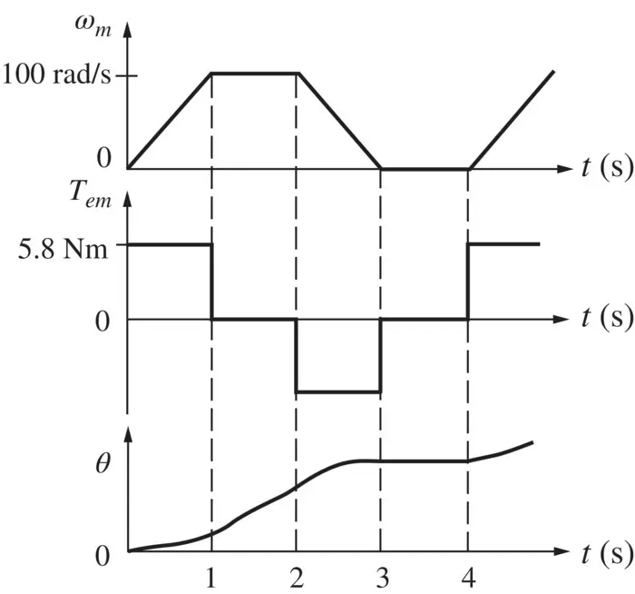
Fig. 2-8 Speed, torque, and angle variations with time.
In a rotational system shown in Fig. 2-9, if a net torque T causes the cylinder to rotate by a differential angle dθ , the differential work done is
(2-26) 
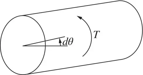
Fig. 2-9 Torque, work, and power.
If this differential rotation takes place in a differential time dt , the power can be expressed as
(2-27) 
where ω m= dθ / dt is the angular speed of rotation. Substituting for T from Eq. (2-21)into Eq. (2-27),
(2-28) 
Integrating both sides of Eq. (2-28)with respect to time, assuming that the speed ω mand the kinetic energy W at the time t = 0 are both zero, the kinetic energy stored in the rotating mass of inertia J is
(2-29) 
This stored kinetic energy can be recovered by making the power p ( t ) reverse direction, that is, by making p ( t ) negative.
In Example 2-3, calculate the kinetic energy stored in the combined inertia at a speed of 1800 rpm.
From Eq. (2-29),

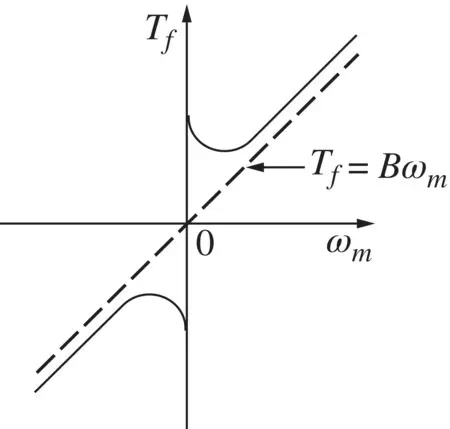
Friction within the motor and the load acts to oppose rotation. Friction occurs in the bearings that support rotating structures. Moreover, moving objects in air encounter windage or drag. In vehicles, this drag is a major force that must be overcome. Therefore, friction and windage can be considered as opposing forces or torque that must be overcome. The frictional torque is generally nonlinear in nature. We are all familiar with the need for a higher force (or torque) in the beginning (from rest) to set an object in motion. This friction at zero speed is called stiction. Once in motion, the friction may consist of a component called Coulomb friction, which remains independent of speed magnitude (it always opposes rotation), as well as another component called viscous friction, which increases linearly with speed.
In general, the frictional torque T fin a system consists of all of the aforementioned components. An example is shown in Fig. 2-10; this friction characteristic may be linearized for an approximate analysis by means of the dotted line. With this approximation, the characteristic is similar to that of viscous friction in which
(2-30) 
where B is the coefficient of viscous friction or viscous damping.
The aerodynamic drag force in automobiles can be estimated as f L= 0.046 C w A u 2, where the coefficient 0.046 has the appropriate units, the drag force is in N , C wis the drag coefficient (a unit‐less quantity), A is the vehicle cross‐sectional area in m 2, and u is the sum of the vehicle speed and headwind in km/h [1]. If A = 1.8 m 2for two vehicles with C w= 0.3 and C w= 0.5, respectively, calculate the drag force and the power required to overcome it at the speeds of 50 and 100 km/h.
The drag force is f L= 0.046 C w Au 2and the power required at the constant speed, from Eq. (2-6), is P = f L u where the speed is expressed in m/s. Table 2-1lists the drag force and the power required at various speeds for the two vehicles. Since the drag force F Ldepends on the square of the speed, the power depends on the cube of the speed.
Traveling at 50 km/h, compared to 100 km/h, requires 1/8th of the power, but it takes twice as long to reach the destination. Therefore, the energy required at 50 km/h would be 1/4th that at 100 km/h.
Читать дальше
