George F. Elmasry - Dynamic Spectrum Access Decisions
Здесь есть возможность читать онлайн «George F. Elmasry - Dynamic Spectrum Access Decisions» — ознакомительный отрывок электронной книги совершенно бесплатно, а после прочтения отрывка купить полную версию. В некоторых случаях можно слушать аудио, скачать через торрент в формате fb2 и присутствует краткое содержание. Жанр: unrecognised, на английском языке. Описание произведения, (предисловие) а так же отзывы посетителей доступны на портале библиотеки ЛибКат.
- Название:Dynamic Spectrum Access Decisions
- Автор:
- Жанр:
- Год:неизвестен
- ISBN:нет данных
- Рейтинг книги:3 / 5. Голосов: 1
-
Избранное:Добавить в избранное
- Отзывы:
-
Ваша оценка:
Dynamic Spectrum Access Decisions: краткое содержание, описание и аннотация
Предлагаем к чтению аннотацию, описание, краткое содержание или предисловие (зависит от того, что написал сам автор книги «Dynamic Spectrum Access Decisions»). Если вы не нашли необходимую информацию о книге — напишите в комментариях, мы постараемся отыскать её.
dynamic spectrum access approach using the latest applications and techniques
Dynamic Spectrum Access Decisions: Local, Distributed, Centralized and Hybrid Designs Dynamic Spectrum Access Decisions · Licensed spectrum bands
· Unlicensed spectrum bands
· Civilian communications
· Military communications
Consisting of a set of techniques derived from network information theory and game theory, DSA improves the performance of communications networks. This book addresses advanced topics in this area and assumes basic knowledge of wireless communications.
Dynamic Spectrum Access Decisions — читать онлайн ознакомительный отрывок
Ниже представлен текст книги, разбитый по страницам. Система сохранения места последней прочитанной страницы, позволяет с удобством читать онлайн бесплатно книгу «Dynamic Spectrum Access Decisions», без необходимости каждый раз заново искать на чём Вы остановились. Поставьте закладку, и сможете в любой момент перейти на страницу, на которой закончили чтение.
Интервал:
Закладка:
3.17 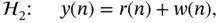
3.18 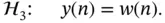
Same‐channel in‐band sensing and the presence of the communications signal's marks such as preambles should lead the ROC model to minimizing P F, with very low probability that the receiver falsely decides that the preamble exist when it does not exist. 12With same‐channel in‐band detection, P Fis the probability of deciding an interfering signal r exists when it does not exist. The key here is to have a good estimation of the noise floor energy and a good estimation of the communication signal energy in order to effectively hypothesize the presence or the absence of an interfering signal.
Let us consider one of the most suitable signal types for same‐channel in‐band sensing with minimal computational power requirements. This is the n ‐ary phase shift keying (PSK) signal type 13. This signal can be used with OFDM as 4‐ary PSK when noise level is high to increase range and reduce data rate, or it can be used as 8‐ary PSK when noise level is low and the signal needs to achieve a higher transmission rate. 14This signal is depicted in Figure 3.3with the 4‐ary case encoding two bits per symbol and the 8‐ary case encoding three bits per symbol.
Figure 3.34‐ary PSK and 8‐ary PSK.
Notice that using two‐dimensional signal space as in Figure 3.3is proven to reduce computational complexity with signal encoding and decoding. Also, PSK makes the signal amplitude change due to noise or interfering signals, not affect the symbol decoding process as shown in Figure 3.4where the decision zones are depicted with dashed lines. Figure 3.5shows the probability distribution function (PDF) contours of one of the signal symbols, S 1, in relation to the decision line (perpendicular bisector) between S 1and S 0. Notice in Figures 3.4and 3.5how the received signal vector, v , minor phase shifting will not cause a probability of a symbol error and how amplitude increase or decrease will never affect symbol errors. With this signal type, symbol error occurs only with considerable phase shifting. This modulation technique is widely used with military communications signals and can be useful in adding same‐channel in‐band sensing to the existing communications signal.
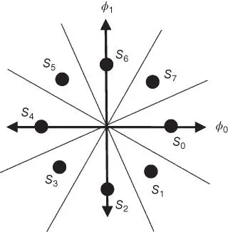
Figure 3.4Decisions zones for 8‐ary PSK.
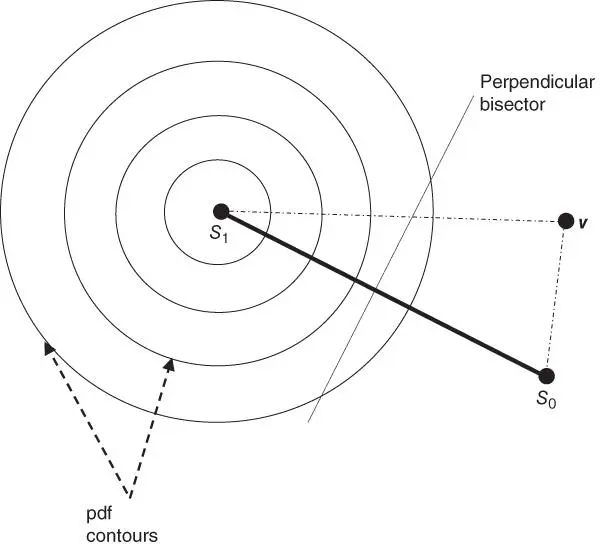
Figure 3.5PDF contour of a PSK signal and perpendicular bisector between two symbols in signal space.
Same‐channel in‐band sensing of n ‐ary PSK signals leverages the signal characteristics where the hypotheses in Equations (3.15)– (3.18)can be simplified. The left‐hand side of Figure 3.6shows how the inner grey circle can define a noise floor (similar to a decision zone for the presence of only noise) and how a measured signal power outside of the outer circle can define an interfering signal that drastically affected the signal amplitude. The right‐hand side of Figure 3.6shows how these circles can be projected into decision lines (thresholds) in terms of the energy detection. Keep in mind that a major difference between symbol decoding and energy detection is that energy detection projects the signal vector into a one‐dimensional positive axis shown as the signal energy axis on the right of Figure 3.6, while symbol decoding deals with the signal based on it SiS dimensions and characteristics.
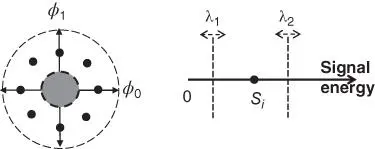
Figure 3.6Hypothesizing the presence of noise and interfering signal with PSK signals.
The approach illustrated in Figure 3.6allows for the estimation of noise floor when the preamble is not acquired and the energy level is low. Noise floor estimation can be a moving average such that the inner dashed line on the left of Figure 3.6, which maps to λ 1for the noise energy threshold, is an adaptable threshold. Similarly, the λ 2threshold defines the separation between a signal and noise versus a signal plus noise plus an interfering signal. λ 2can be adapted as the noise floor estimation changes and as the estimated received signal power is changed. 15Notice that if the communications waveform has an adaptable power control feature, knowledge of the signal transmission power, the distance between the transmitter and the sensor, and the terrain type can help decide where λ 2changes adaptively.
Equations (3.15)– (3.18) and Figure 3.6explain an overlay concept of the noise, in‐band signal, and interfering signal. If the noise floor estimation is accurate, the sensor can subtract w ( n ) from Equations (3.11)– (3.14). If the sensor has information regarding the transmission power of the in‐band signal, the distance to the emitter and terrain information, then s ( n ) can be estimated, allowing the sensor to hypothesize the presence of an interfering signal in a close to optimal way. 16
It is critical to understand the importance of collecting large samples by the spectrum sensor to make the ROC model viable in implementation. More importantly, noise and the interfering signal are manifested not by a simple increase in energy detection level, but by an increase in the variance of the collected samples. Relying on a small sample can lead to suboptimal results as the set of small samples can be misleading. Estimating the deviation in the energy samples is what accurately reflects the impact of noise and interfering signals and what should be used for dynamically adapting the thresholds.
3.3 Decision Fusion
The ROC model implementation at the sensing node could be the first step towards making spectrum sensing decisions. The next step is referred to as decision fusion (DF), which uses the ROC model hypotheses outcome to make more comprehensive spectrum sensing decisions. This section presents local, distributed, and centralized decision fusion approaches to help the reader decide the most suitable place to make a DSA decision in a hybrid DSA system.
3.3.1 Local Decision Fusion
With a spectrum sensor performing a simple energy detection decision, this may be the end of the decision‐making process that can be made locally. The local decision fusion process would rely on the local hypotheses that differentiate if the frequency band being sensed is occupied or not. If a hypothesis is persistent for the presence or absence of a signal, the decision fusion will turn the hypotheses into a decision. However, if an augmented sensor is able to utilize a multisector antenna or antenna arrays, there could be further fusion steps before making a decision. An example of a further fusion step is to identify the direction of the interfering signal when the local process hypothesizes the presence of interference relying on the difference in the energy received per sector. This case is covered in Section 3.3.1.2The more common case to perform further local decision fusion is for the same‐channel in‐band sensing in a MANET where the reception of the sensed communications signal can be mapped to an RF neighbor. This can make the spectrum sensor in the MANET node able to create a more detailed spectrum map (i.e., identify interference directionality) without using sectored antennas, 17as explained in Section 3.3.1.1
Читать дальшеИнтервал:
Закладка:
Похожие книги на «Dynamic Spectrum Access Decisions»
Представляем Вашему вниманию похожие книги на «Dynamic Spectrum Access Decisions» списком для выбора. Мы отобрали схожую по названию и смыслу литературу в надежде предоставить читателям больше вариантов отыскать новые, интересные, ещё непрочитанные произведения.


Обсуждение, отзывы о книге «Dynamic Spectrum Access Decisions» и просто собственные мнения читателей. Оставьте ваши комментарии, напишите, что Вы думаете о произведении, его смысле или главных героях. Укажите что конкретно понравилось, а что нет, и почему Вы так считаете.