George F. Elmasry - Dynamic Spectrum Access Decisions
Здесь есть возможность читать онлайн «George F. Elmasry - Dynamic Spectrum Access Decisions» — ознакомительный отрывок электронной книги совершенно бесплатно, а после прочтения отрывка купить полную версию. В некоторых случаях можно слушать аудио, скачать через торрент в формате fb2 и присутствует краткое содержание. Жанр: unrecognised, на английском языке. Описание произведения, (предисловие) а так же отзывы посетителей доступны на портале библиотеки ЛибКат.
- Название:Dynamic Spectrum Access Decisions
- Автор:
- Жанр:
- Год:неизвестен
- ISBN:нет данных
- Рейтинг книги:3 / 5. Голосов: 1
-
Избранное:Добавить в избранное
- Отзывы:
-
Ваша оценка:
Dynamic Spectrum Access Decisions: краткое содержание, описание и аннотация
Предлагаем к чтению аннотацию, описание, краткое содержание или предисловие (зависит от того, что написал сам автор книги «Dynamic Spectrum Access Decisions»). Если вы не нашли необходимую информацию о книге — напишите в комментариях, мы постараемся отыскать её.
dynamic spectrum access approach using the latest applications and techniques
Dynamic Spectrum Access Decisions: Local, Distributed, Centralized and Hybrid Designs Dynamic Spectrum Access Decisions · Licensed spectrum bands
· Unlicensed spectrum bands
· Civilian communications
· Military communications
Consisting of a set of techniques derived from network information theory and game theory, DSA improves the performance of communications networks. This book addresses advanced topics in this area and assumes basic knowledge of wireless communications.
Dynamic Spectrum Access Decisions — читать онлайн ознакомительный отрывок
Ниже представлен текст книги, разбитый по страницам. Система сохранения места последней прочитанной страницы, позволяет с удобством читать онлайн бесплатно книгу «Dynamic Spectrum Access Decisions», без необходимости каждый раз заново искать на чём Вы остановились. Поставьте закладку, и сможете в любой момент перейти на страницу, на которой закончили чтение.
Интервал:
Закладка:
1 Creating a contrast between S(t) and W(t) such that when S(t) is present at a time t, the output of the filter will have a large peak
2 Minimizing the probability of error. This can be achieved by considering the energy of the signal and the energy of the noise over a time T instead of considering the signal and noise amplitude. Energy calculation uses the square of the amplitude.
Notice that with wireless communications systems where we decode symbols, minimizing the probability of symbol error also uses signal and noise energy. However, the probability of error in spectrum sensing has two folds. With spectrum sensing, we have a probability of false alarm where the matched filter decides that S ( t ) is detected but S ( t ) was absent and the probability of misdetection where the matched filter decides that S ( t ) is absent but S ( t ) was present. 9
Figure 2.7shows the use of a matched filter to detect the presence of a signal S ( t ). Notice that a spectrum sensor can sense more than one signal type using a bank of matched filters. Once the spectrum sensor decides the signal type, other signal synthesizing techniques can be used to discover characteristics such as spreading code or orthogonality.
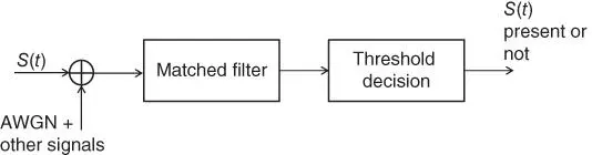
Figure 2.7Signal detection using matched filters.
Some of the disadvantages of the matched filter sensing technique include the following:
The implementation complexity may not be practical to implement for a large set of signals. Consider the detection of all types of commercial cellular signals and other known commercial but not cellular signals.
Large power consumption is needed to execute the various receiver algorithms.
2.4.2 Autocorrelation Based Spectrum Sensing
This spectrum sensing approach has more advantages than the matched filter approach described in the previous section when attempting to detect the presence of a narrow band signal. Autocorrelation estimation can result in a constant false alarm rate (CFAR) by employing techniques that reduce the dependency on noise power. With this sensing technique, the sensor can have a stored representation of the signal as samples S ( t ) = ( s 0, s 1, …, s N − 1) or has a signal generator that can generate a copy of the sensed signal and sample it. The sensed signal S *( t ) is sampled to produce 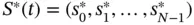 . The result of the correlation process 10between S ( t ) and S *( t ) is compared to threshold to decide if the sensed signal matches S ( t ) or not, as shown in Figure 2.8.
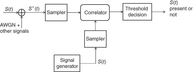
Figure 2.8Signal detection using autocorrelation.
If the sensor uses a signal generator and a sampler instead of stored samples, as in Figure 2.8, the sampler can be broken down as shown in Figure 2.9where down conversion and a low pass filter (LPF) is used before time sampling. 11In Figure 2.9, the signal is a complex baseband signal with center frequency f c. The LPF has a bandwidth of (− f bw, f bw) Hz and the sampling rate is 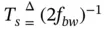 .
.
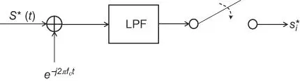
Figure 2.9Signal sampling before autocorrelation.
The correlation technique attempts to produce unbiased estimation of the signal that can be expressed in terms of a variable l that is adaptively chosen to reduce noise power dependency. Different techniques can be employed to incorporate l in the correlation function, such as estimating a covariance matrix.
Autocorrelation based spectrum sensing can use a bank of signal generators, samplers, and correlators to detect the presence of multiple signals.
Notice the difference between time‐domain cyclic marks and frequency domain cyclic marks. OFDM signals use a frequency‐domain cyclic prefix, which protects the OFDM signals 12from inter‐symbol interference. This cyclic prefix can be utilized in a frequency‐domain based correlation technique to affirm the presence of the targeted signal. If the targeted signal uses a preamble of symbols, this preamble can be utilized to affirm the presence of the signal in time‐domain correlation. Both cyclic prefix and time‐domain preamble can help the autocorrelation capable sensor decrease the probability of misdetection and the probability of false alarm when making a decision regarding the presence of the targeted signal.
2.4.3 Spreading Code Spectrum Sensing
Spread spectrum is implemented differently in commercial signals than in military signals. Commercial signals tend to use direct sequence spread spectrum, which is easy to sense, while military signals tend to use frequency hopping spread spectrum, which is intentionally made hard to detect.
Figure 2.10shows the commercial case where a chip code C nis module‐2 added to the signal binary stream X nbefore modulation. The resulting binary stream m nis a pseudo random sequence. The modulated signal s ( t ) is a spread spectrum signal.
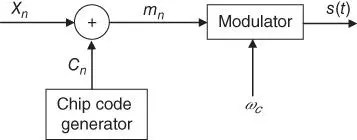
Figure 2.10Direct sequence spread spectrum modulation.
Figure 2.11shows a frequency hopping spread spectrum, which divides the available spectrum into slots. The carrier frequency then hops among these slots at a rate that is known as the frequency hopping rate. The hopping range of W Hertz is divided it into N slots with each slot size being Δf . The carrier frequency is always decided by the frequency synthesizer at each moment. The synthesizer is driven by a pseudorandom generator which generates unique N input vectors to the frequency synthesizer.
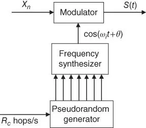
Figure 2.11Frequency‐hopping spread spectrum signal modulation.
With Figure 2.11, a pseudorandom generator, clocked at the hopping rate R c, feeds the frequency synthesizer. The frequency synthesizer generates the hopping carrier frequency for the modulator expressed as cos( ω i t + θ ). Notice that the binary stream X nis modulated over the carrier with frequency ω i, which corresponds to the i th slot of the N slots available for hopping. The hopping rate is determined by R c.
When autocorrelation detection is used and the presence of the targeted signal is hypothesized to exist, the spectrum sensor can use a chip code generator to generate all the chip codes the targeted signal is known to use. One of the chip codes that is used by the targeted signal will result in the highest correlation with the sensed signal. The spectrum sensor may be able to help the local DSA decision fusion agent pinpoint which chip code is not used in a certain vicinity at a certain time, allowing for the opportunistic use 13of the sensed frequency band only with an unused chip code.
Читать дальшеИнтервал:
Закладка:
Похожие книги на «Dynamic Spectrum Access Decisions»
Представляем Вашему вниманию похожие книги на «Dynamic Spectrum Access Decisions» списком для выбора. Мы отобрали схожую по названию и смыслу литературу в надежде предоставить читателям больше вариантов отыскать новые, интересные, ещё непрочитанные произведения.


Обсуждение, отзывы о книге «Dynamic Spectrum Access Decisions» и просто собственные мнения читателей. Оставьте ваши комментарии, напишите, что Вы думаете о произведении, его смысле или главных героях. Укажите что конкретно понравилось, а что нет, и почему Вы так считаете.