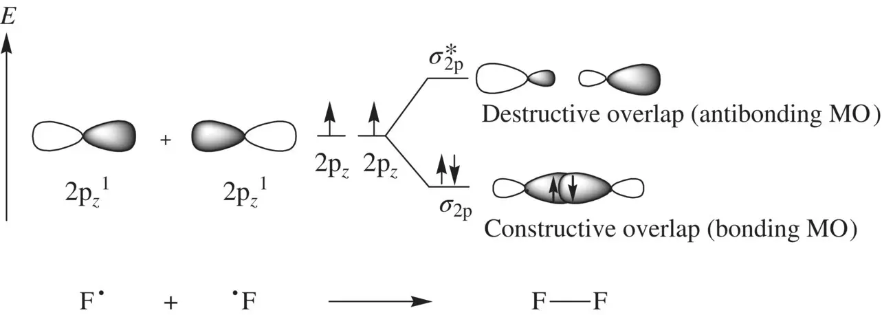
FIGURE 1.9 Formation of the fluorine molecule (F 2) from two fluorine (F) atoms.
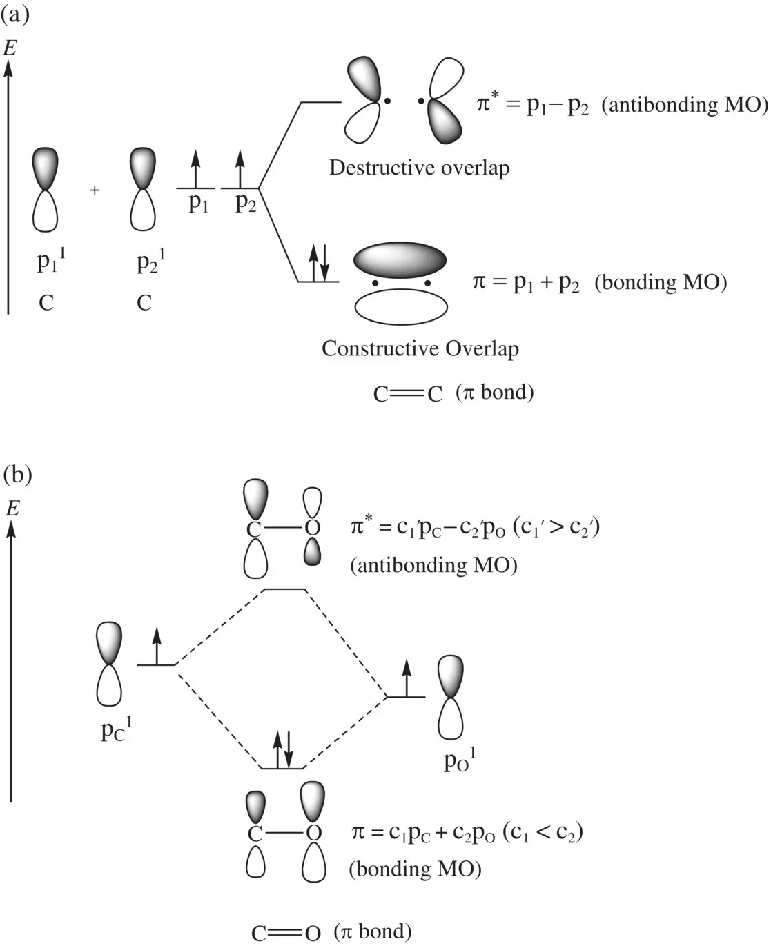
FIGURE 1.10 Formation of (a) the C=C π bond from two equivalent p orbitals and (b) the C=O π bond from two nonequivalent p orbitals.


The above equations show that for the formation of π p, the p orbital in oxygen (more electronegative) makes a greater contribution than does the p orbital in carbon (less electronegative). For the formation of π p *, the p orbital in carbon (less electronegative) makes a greater contribution than does the p orbital in oxygen (more electronegative). In each case, the bonding π pMO is responsible for the formation of a π bond, and antibonding orbital π p *is responsible for dissociation of the π bond.
When more than two p orbitals overlap sideways, it results in the formation of a conjugate π bond. Similar to the separate π bonds (formed by sideway overlap of two p orbitals), a conjugate π bond consists of series of MOs formed by linear combinations of the contributing p orbitals. The number of constituent MOs is equal to the number of contributing p orbitals. For example, the conjugate π‐bond of allyl radical (CH 2=CHCH 2˙), formed by sideway overlap of three p orbitals in the carbon atoms, consists of the following three MOs ( Fig. 1.11a):


The conjugate π‐bond of 1,3‐butadiene (CH 2=CHCH=CH 2), formed by sideway overlap of four p orbitals in the carbon atoms, consists of the following four MOs ( Fig. 1.11b):


In each of the molecules, since all the p orbitals are from carbon atoms, their contributions to each of the MOs are equal.
1.8.2 Molecular Orbital Diagrams
When two AOs combine linearly (overlap) to form MOs (Figs ), the bonding MO formed by positive LCAO has lower energy than each of the starting AOs, while the antibonding MO formed by negative LCAO possesses higher energy than the AOs [4, 5]. As a result, the electrons from the starting AOs flow into the lower‐energy‐level bonding MO upon the formation of the molecule and the antibonding MO with a higher energy level remains empty. The overall energy decreases. The diagrams showing correlations of AOs and the resulting MOs and their relative energy levels are called molecular orbital diagrams. Figs show the MO diagrams for the formation of H 2from hydrogen atoms, the formation of F 2from fluorine atoms, and the formation of a π‐bond from p orbitals. All the MO diagrams clearly indicate the energy gains (driving forces) for the formation of a molecule (or a bond) from individual atoms. Figure 1.11shows MO diagrams for the formation of a conjugate π‐bond from p orbitals. The MO diagrams also indicate that any MOs whose energies are lower than those of the starting AOs are bonding orbitals, responsible for the formation of the molecule. If an MO has the same energy as that of a starting AO, it is a nonbonding orbital which does not make any contribution to the formation of the molecule. Any MOs whose energies are higher than those of the starting AOs are antibonding orbitals, responsible for the dissociation of the molecule if they are populated with electrons [5].
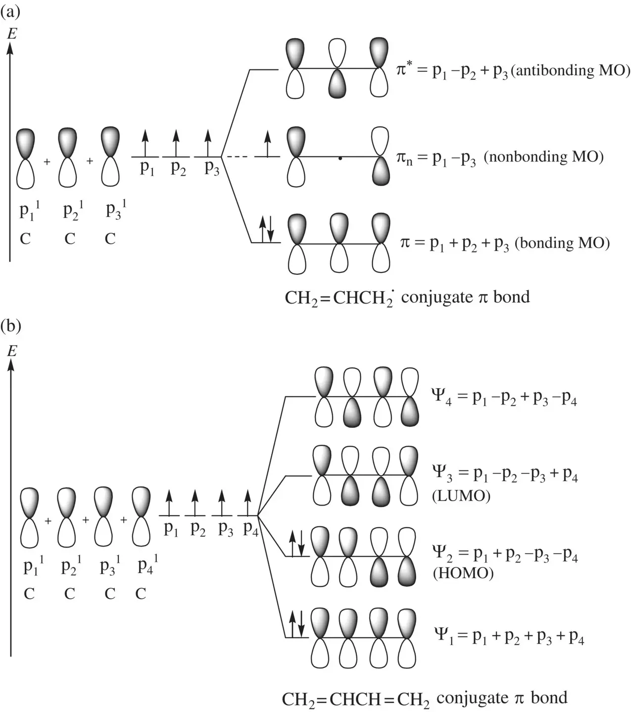
FIGURE 1.11 Formation of conjugate π bonds from p orbitals in (a) the allyl radical (CH 2=CHCH 2˙) and (b) the 1,3‐butadiene (CH 2=CHCH=CH 2) molecule.
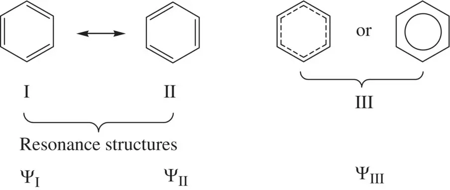
FIGURE 1.12 Resonance stabilization of benzene.
1.8.3 Resonance Stabilization
By the nature, resonance stabilizationis a result of electron delocalization in a molecule, which leads to decrease in energy and stabilizes the molecule. It typically occurs in the p πsystems. First, we will use the benzene molecule as an example to demonstrate the nature of resonance stabilization.
Figure 1.12shows two valid Lewis structures (I and II) for benzene [4]. Each of them has alternating double bond and single bond in the ring structure. Since six π electrons in the molecule are delocalized along the ring via the sideway overlap of six p orbitals forming a conjugate π bond and all the C─C bonds are of equal length, neither of the Lewis structures alone can truly describe the geometry and the real electronic configuration of the benzene molecule. Due to delocalization of the π electrons, the real electronic configuration can be considered resonating between the Lewis structures I and II, which are called resonance structures. In other words, the real structure and electronic configuration of benzene contain characters of both resonance structures and can be thought the average of the two. The bond order of each of the C─C bonds is 1.5, which is between a single bond (b.o. = 1) and a double bond (b.o. = 2). This way of characterization of benzene using two resonance structures I and II is consistent with the consequence of the π electrons delocalization as described by structure III. Therefore, the real wavefunction of the benzene molecule Ψ IIIcan be formulated as the linear combination of the wavefunctions of structures I and II (Ψ Iand Ψ II, respectively) [4]:

Since the structures I and II are equivalent, the contributions of both Lewis structures to the real structure of the benzene molecule should be equal. Therefore, we have a = b. Due to the electron delocalization, the real structure III has lower energy than that of structure I or II. Such stabilization by electron delocalization is called resonance stabilization.
Читать дальше
