Malcolm J. Crocker - Engineering Acoustics
Здесь есть возможность читать онлайн «Malcolm J. Crocker - Engineering Acoustics» — ознакомительный отрывок электронной книги совершенно бесплатно, а после прочтения отрывка купить полную версию. В некоторых случаях можно слушать аудио, скачать через торрент в формате fb2 и присутствует краткое содержание. Жанр: unrecognised, на английском языке. Описание произведения, (предисловие) а так же отзывы посетителей доступны на портале библиотеки ЛибКат.

- Название:Engineering Acoustics
- Автор:
- Жанр:
- Год:неизвестен
- ISBN:нет данных
- Рейтинг книги:3 / 5. Голосов: 1
-
Избранное:Добавить в избранное
- Отзывы:
-
Ваша оценка:
Engineering Acoustics: краткое содержание, описание и аннотация
Предлагаем к чтению аннотацию, описание, краткое содержание или предисловие (зависит от того, что написал сам автор книги «Engineering Acoustics»). Если вы не нашли необходимую информацию о книге — напишите в комментариях, мы постараемся отыскать её.
Engineering Acoustics — читать онлайн ознакомительный отрывок
Ниже представлен текст книги, разбитый по страницам. Система сохранения места последней прочитанной страницы, позволяет с удобством читать онлайн бесплатно книгу «Engineering Acoustics», без необходимости каждый раз заново искать на чём Вы остановились. Поставьте закладку, и сможете в любой момент перейти на страницу, на которой закончили чтение.
Интервал:
Закладка:
where k = ω /c = 2π f/c (the wavenumber).
The first term in Eq. (3.88)represents a wave of amplitude  traveling in the + x‐ direction. The second term in Eq. (3.88)represents a wave of amplitude
  traveling in the − x‐ direction.
The equivalent expression to Eq. (3.88)using complex notation is
(3.89) 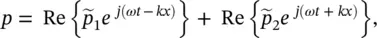
where  , Re{} means real part; and
  and
and  are complex amplitudes of the sound pressure; remember k = ω /c ; kc = 2π f . Both Eqs. (3.88)and (3.89)are solutions to Eq. (3.86).
For the three‐dimensional case ( x , y , and z propagation), the sinusoidal (pure tone) solution to Eq. (3.87)is
(3.90) 
Note that there are 2 3(eight) possible solutions given by Eq. (3.90). Substitution of Eq. (3.90)into Eq. (3.87)(the three‐dimensional wave equation) gives (from any of the eight (2 3) equations):
(3.91) 
from which the wavenumber k is
(3.92) 
and the so‐called direction cosines with the x , y and z directions are cos θ x= ± k x /k , cos θ y= ± k y /k , and cos θ z= ± k z /k (see Figure 3.32).
Figure 3.32 Direction cosines and vector k .
Equations (3.91)and (3.92)apply to the cases where the waves propagate in unbounded space (infinite space) or finite space (e.g. rectangular rooms).
For the case of rectangular rooms with hard walls, we find that the sound (particle) velocity perpendicular to each wall must be zero. By using these boundary conditions in each of the eight solutions to Eq. (3.87), we find that ω 2= (2 πf ) 2and k 2in Eqs. (3.91)and (3.92)are restricted to only certain discrete values:
(3.93) 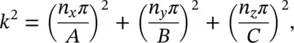
or

Then the room natural frequencies are given by
(3.94) 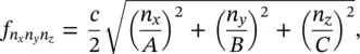
where A , B , C are the room dimensions in the x , y , and z directions, and n x= 0, 1, 2, 3, … ; n y= 0, 1, 2, 3, … and n z= 0, 1, 2, 3, … Note n x, n y, and n zare the number of half waves in the x , y , and z directions. Note also for the room case, the eight propagating waves add together to give us a standing wave. The wave vectors for the eight waves are shown in Figure 3.33.
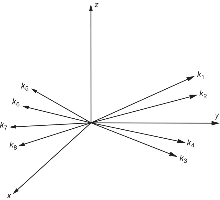
Figure 3.33 Wave vectors for eight propagating waves.
There are three types of standing waves resulting in three modes of sound wave vibration: axial, tangential, and oblique modes. Axial modes are a result of sound propagation in only one room direction. Tangential modes are caused by sound propagation in two directions in the room and none in the third direction. Oblique modes involve sound propagation in all three directions.
We have assumed there is no absorption of sound by the walls. The standing waves in the room can be excited by noise or pure tones. If they are excited by pure tones produced by a loudspeaker or a machine that creates sound waves exactly at the same frequency as the eigenfrequencies (natural frequencies) f Eof the room, the standing waves are very pronounced. Figures 3.34and 3.35show the distribution of particle velocity and sound pressure for the n x= 1, n y= 1, and n z= 1 mode in a room with hard reflecting walls. See Refs. [23, 24] for further discussion of standing‐wave behavior in rectangular rooms.
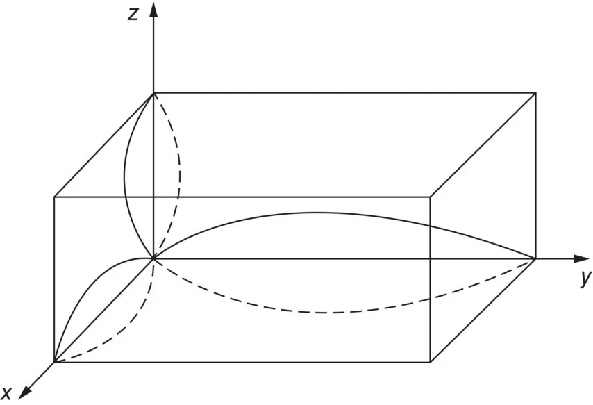
Figure 3.34 Standing wave for n x= 1, n y= 1, and n z= 1 (particle velocity shown).
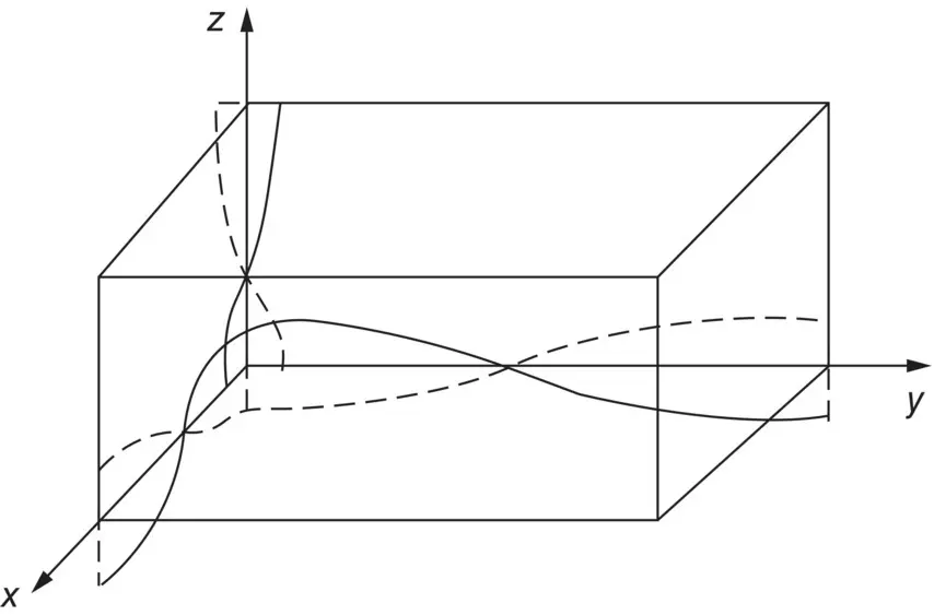
Figure 3.35 Standing wave for n x= 1, n y= 1, and n z= 1 (sound pressure shown).
Example 3.16
Calculate all the possible natural frequencies for normal modes of vibration under 100 Hz within a rectangular room 3.1 × 4.7 × 6.2 m 3.
Solution
Table 3.3gives all the possible natural frequencies for modes under 100 Hz using Eq. (3.94)and c = 343 m/s.
One can see in Table 3.3that the frequency spacing becomes smaller with increasing frequency and that there may be degenerate modes present (i.e. when two or more modes have the same characteristic frequency but different values of n x, n y, and n z). Modes which are close to each other in frequency can easily “beat,” while degenerate modes can greatly increase the response of the room at particular frequencies where degeneracy occurs. This can give rise to the “boomy” sensation (at low frequencies) which is often found in regular‐shaped rooms of similar wall dimensions [4].
Table 3.3 Frequencies (less than 100 Hz) for a 3.1 × 4.7 × 6.2 m 3rectangular room, for c = 343 m/s.
| n x | n y | n z | f E |
|---|---|---|---|
| 0 | 0 | 1 | 27.7 |
| 0 | 1 | 0 | 36.5 |
| 0 | 1 | 1 | 45.8 |
| 0 | 0 | 2 | } 55.3 |
| 1 | 0 | 0 | |
| 1 | 0 | 1 | 61.9 |
| 0 | 1 | 2 | } 66.3 |
| 1 | 1 | 0 | |
| 1 | 1 | 1 | 71.8 |
| 0 | 2 | 0 | 73.0 |
| 1 | 0 | 2 | 78.2 |
| 0 | 2 | 1 | 78.0 |
| 0 | 0 | 3 | 83.0 |
| 1 | 1 | 2 | 86.3 |
| 0 | 1 | 3 | 90.7 |
| 0 | 2 | 2 | } 91.6 |
| 1 | 2 | 0 | |
| 1 | 2 | 1 | 95.7 |
| 1 | 0 | 3 | 99.7 |
The position of the sound source within the room is also an important parameter, since for many source positions certain types of modes may not be excited. For example, if the source is located in one of the corners of the room, then it is possible to excite every normal mode, while if the source is located at the center of a rectangular room then only the even modes (one eighth of the total number of possible modes) can be excited. Similarly if we keep the position of the source constant and measure the sound pressure throughout the room we see differences in level depending on where we are standing in the room relative to the normal modes. In this way the room superimposes its own acoustical response characteristics upon those of the source. Hence we cannot measure the true frequency response of a sound source (e.g. loudspeaker) in a reverberant room because of the effect of the modal response of the room. This interference can be removed by making all the wall surfaces highly sound‐absorbent. Then all the modes are sufficiently damped so we are able to measure the true output of the source [4]. Such rooms are called anechoic (see Figure 3.22).
Читать дальшеИнтервал:
Закладка:
Похожие книги на «Engineering Acoustics»
Представляем Вашему вниманию похожие книги на «Engineering Acoustics» списком для выбора. Мы отобрали схожую по названию и смыслу литературу в надежде предоставить читателям больше вариантов отыскать новые, интересные, ещё непрочитанные произведения.


Обсуждение, отзывы о книге «Engineering Acoustics» и просто собственные мнения читателей. Оставьте ваши комментарии, напишите, что Вы думаете о произведении, его смысле или главных героях. Укажите что конкретно понравилось, а что нет, и почему Вы так считаете.