Plastics Process Analysis, Instrumentation, and Control
Здесь есть возможность читать онлайн «Plastics Process Analysis, Instrumentation, and Control» — ознакомительный отрывок электронной книги совершенно бесплатно, а после прочтения отрывка купить полную версию. В некоторых случаях можно слушать аудио, скачать через торрент в формате fb2 и присутствует краткое содержание. Жанр: unrecognised, на английском языке. Описание произведения, (предисловие) а так же отзывы посетителей доступны на портале библиотеки ЛибКат.

- Название:Plastics Process Analysis, Instrumentation, and Control
- Автор:
- Жанр:
- Год:неизвестен
- ISBN:нет данных
- Рейтинг книги:3 / 5. Голосов: 1
-
Избранное:Добавить в избранное
- Отзывы:
-
Ваша оценка:
Plastics Process Analysis, Instrumentation, and Control: краткое содержание, описание и аннотация
Предлагаем к чтению аннотацию, описание, краткое содержание или предисловие (зависит от того, что написал сам автор книги «Plastics Process Analysis, Instrumentation, and Control»). Если вы не нашли необходимую информацию о книге — напишите в комментариях, мы постараемся отыскать её.
Process analysis is the starting point since plastics processing is different from processing of metals, ceramics, and other materials. Plastics materials show unique behavior in terms of heat transfer, fluid flow, viscoelastic behavior, and a dependence of the previous time, temperature and shear history which determines how the material responds during processing and its end use. Many of the manufacturing processes are continuous or cyclical in nature. The systems are flow systems in which the process variables, such as time, temperature, position, melt and hydraulic pressure, must be controlled to achieve a satisfactory product which is typically specified by critical dimensions and physical properties which vary with the processing conditions.
Instrumentation has to be selected so that it survives the harsh manufacturing environment of high pressures, temperatures and shear rates, and yet it has to have a fast response to measure the process dynamics. At many times the measurements have to be in a non-contact mode so as not to disturb the melt or the finished product. Plastics resins are reactive systems. The resins will degrade if the process conditions are not controlled. Analysis of the process allows one to strategize how to minimize degradation and optimize end-use properties.
Plastics Process Analysis, Instrumentation, and Control — читать онлайн ознакомительный отрывок
Ниже представлен текст книги, разбитый по страницам. Система сохранения места последней прочитанной страницы, позволяет с удобством читать онлайн бесплатно книгу «Plastics Process Analysis, Instrumentation, and Control», без необходимости каждый раз заново искать на чём Вы остановились. Поставьте закладку, и сможете в любой момент перейти на страницу, на которой закончили чтение.
Интервал:
Закладка:
The current technology further includes directly incorporating a heating unit in the mold. However, such a mold necessitates a reconnection of the wirings of the hot plate when the mold is being replaced; hence, the mold replacement process becomes more complicated. Furthermore, incorporating a heating unit in the mold increases the fabrication cost and the removable heating pipelines also present safety issues (56).
So, a mold thermal controlling device for efficiently heating or cooling a mold was developed (56). Figure 1.5is a schematic view illustrating a mold thermal controlling device and a mold.
The injection end 232 and the discharge end 234 pierce through the first temperature control layer, and the heated or cold liquid is injected through the injection end 232 and is discharged from the discharge end 234. Since the replacement of the mold 110 does not require any changes to the temperature control tunnel 230, deterioration of the temperature control tunnel 230 due to frequent changing is reduced, and safety and the replacement efficiency are improved.
In particular, the mold thermal controlling device includes a first trench, a first temperature control layer and at least a temperature control tunnel. The first temperature control layer includes a first temperature control face and the first temperature control layer forms a first temperature control trench forming the inner surface of a part of the first trench. The first temperature control trench is used for accommodating or containing a mold and is in contact with the mold through the first temperature control face. The temperature control tunnel is disposed in the first temperature control layer. A heated fluid or a cold fluid is injected into the temperature control tunnel. When the mold is placed in the first temperature control trench, the first temperature control face is positioned between the mold and the temperature control tunnel.
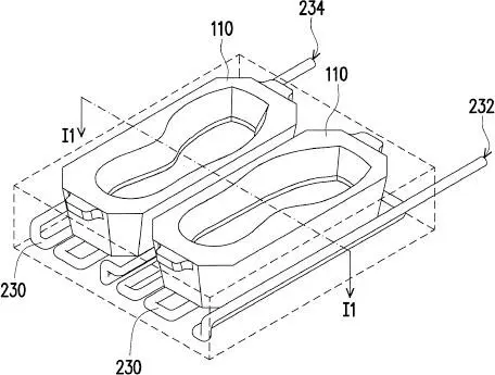
Figure 1.5 Mold thermal controlling device (56).
The mold thermal controlling device further includes a first surface having a first trench, and the opening of the first trench is positioned at the first surface. The cross-sectional area of the first trench tapers from the opening of the first trench along the first direction, and the mold is placed in or removed from the first trench along the first direction.
The mold thermal controlling device applies a pressure to the mold along the first direction. The surfaces of the mold that is in contact with the first temperature control layer protrudes and concaves along the first direction, and the cross section of the opening of the first trench tapers along the first direction. The mold is placed in or removed from the first trench along the first direction.
Since the mold thermal controlling device includes a temperature control tunnel that is formed with the temperature control layer, the temperature control tunnel can efficiently heat or cool the mold placed therein. Moreover, the mold used with the mold thermal controlling device can be easily replaced, and there are structures that may be included in or on the mold to assist the positioning of the mold, the gas discharge or to perform a grabbing action. Additionally, the mold thermal controlling device may be applied to an automated fabrication process. Since the hot press system of the disclosure includes the above mold thermal controlling device, which can provide heating or cooling with high efficiency, the hot press system of the disclosure can be broadly applied to various hot pressing processes (56).
1.14 Stamper Mold
1.14.1 Recoding Media
A stamper for forming a data recording region on a recording medium substrate by means of a transfer surface thereof has been described (57). The transfer surface transfers a predetermined set of data to the recording medium substrate. The stamper is fitted on at least one of the metal molds that are arranged opposite one another for forming the recording medium substrate. The stamper includes a stepped portion formed as bends in the material of the stamper. The stepped portion is configured to project from the transfer surface toward the recording medium substrate.
The substrate may be produced through common injection molding processes and photopolymer processes. The injection molding process is a process in which an acrylic or a PC resin melted by a plasticizer of a molding device is filled into a cavity of a mold fitted with a master disc having microscopic projection/recess patterns for recording/retrieving signals, and the resulting substrate is removed from the mold after the molten resin cools down and is solidified (57).
1.14.2 Microscopic Structured Body
A polymer molded product with a fine structure has been increasingly utilized in various fields such as electronic devices, optical devices, recording media, and medical devices (58). Various methods for manufacturing such a molded product with fine structure have been proposed but attention has been attracted to a UV and thermal nanoimprint method owing to high economic efficiency and productivity. In the case of nanoimprint methods, there is a hot embossing, i.e., a thermal nanoimprint method, in which a stamper mold is pressed to a polymer substrate softened under heating to cause plastic deformation, thereby transfer-molding a pattern of the stamper mold. The hot embossing method shows a high productivity and has advantages such as the capability of fabrication of fine patterns of various thermoplastic polymer substrates.
However, the thermal nanoimprint method has a problem as, in the filling stage of a fine structure of a high aspect ratio, the fluidity of the polymer is insufficient or a high pressure is needed. Also, the hot embossing method has a problem that, when the polymer is heated to the melting temperature, the fluidity of the polymer exceedingly increases and the polymer substrate only undergoes deformation of extending in a plane direction even when pressed, and thus the polymer is not filled into a deep groove portion of the fine structure in which flow resistance is large.
To address this problem, a method of manufacturing a molded product with a nanostructure and a microstructure has been proposed, which includes (59, 60):
1 A step of placing a powdery polymer on the surface of an original plate,
2 A step of heating the original plate and the polymer to a temperature equal to or higher than the glass transition temperature of the polymer and equal to or lower than the melting temperature,
3 A step of pressing the polymer to the original plate, and
4 A step of removing the original plate after cooling the polymer to a temperature equal to or lower than the glass transition temperature so as to form a reverse structure of the nanostructure and microstructure of the original plate.
On the other hand, besides the hot embossing method, there is a UV optical nanoimprint method in which, after a liquid photocurable polymer is coated on a substrate at room temperature, an optically transparent stamper mold is pressed to the polymer and the polymer is irradiated with a light through the stamper mold to cure the polymer, thereby transcribing a pattern onto the polymer substrate. The advantages of the UV optical nanoimprint method are that processing can be performed at room temperature, transcribed pressure is low, and a highly accurate pattern can be molded (58).
However, in the UV optical nanoimprint method, although the pressure for transcription is low, a photocurable polymer generally exhibits a small amount of shrinkage at curing and has properties resembling an adhesive, so that it is difficult to release the imprinted film polymer from the stamper mold and thus there is a concern that a fine structure of the stamper mold will be broken through releasing the imprinted film (58).
Читать дальшеИнтервал:
Закладка:
Похожие книги на «Plastics Process Analysis, Instrumentation, and Control»
Представляем Вашему вниманию похожие книги на «Plastics Process Analysis, Instrumentation, and Control» списком для выбора. Мы отобрали схожую по названию и смыслу литературу в надежде предоставить читателям больше вариантов отыскать новые, интересные, ещё непрочитанные произведения.


Обсуждение, отзывы о книге «Plastics Process Analysis, Instrumentation, and Control» и просто собственные мнения читателей. Оставьте ваши комментарии, напишите, что Вы думаете о произведении, его смысле или главных героях. Укажите что конкретно понравилось, а что нет, и почему Вы так считаете.