Gregory T. Benz - Agitator Design for Gas-Liquid Fermenters and Bioreactors
Здесь есть возможность читать онлайн «Gregory T. Benz - Agitator Design for Gas-Liquid Fermenters and Bioreactors» — ознакомительный отрывок электронной книги совершенно бесплатно, а после прочтения отрывка купить полную версию. В некоторых случаях можно слушать аудио, скачать через торрент в формате fb2 и присутствует краткое содержание. Жанр: unrecognised, на английском языке. Описание произведения, (предисловие) а так же отзывы посетителей доступны на портале библиотеки ЛибКат.

- Название:Agitator Design for Gas-Liquid Fermenters and Bioreactors
- Автор:
- Жанр:
- Год:неизвестен
- ISBN:нет данных
- Рейтинг книги:4 / 5. Голосов: 1
-
Избранное:Добавить в избранное
- Отзывы:
-
Ваша оценка:
Agitator Design for Gas-Liquid Fermenters and Bioreactors: краткое содержание, описание и аннотация
Предлагаем к чтению аннотацию, описание, краткое содержание или предисловие (зависит от того, что написал сам автор книги «Agitator Design for Gas-Liquid Fermenters and Bioreactors»). Если вы не нашли необходимую информацию о книге — напишите в комментариях, мы постараемся отыскать её.
Agitator Design for Gas-Liquid Fermenters and Bioreactors — читать онлайн ознакомительный отрывок
Ниже представлен текст книги, разбитый по страницам. Система сохранения места последней прочитанной страницы, позволяет с удобством читать онлайн бесплатно книгу «Agitator Design for Gas-Liquid Fermenters and Bioreactors», без необходимости каждый раз заново искать на чём Вы остановились. Поставьте закладку, и сможете в любой момент перейти на страницу, на которой закончили чтение.
Интервал:
Закладка:
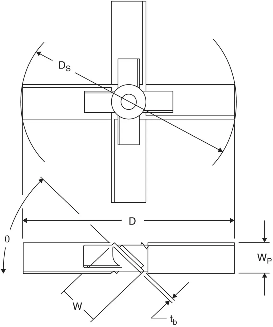
Figure 3.3 Swept diameter.
Tank Dimensions
The tank diameter is designated as T. The liquid level is designated as Z. Other tank dimensions, not shown on the sketch, could include head depths, straight side, nozzle projections, baffles (width, length, and offset from wall), and any relevant internals.
How Agitation Parameters Are Calculated
Agitation systems, just as any other system producing or modifying fluid flow, must obey the laws of physics. In terms of mathematical models, they obey the equations of continuity and the Navier–Stokes equations. Unfortunately, those equations can usually only solve problems analytically in relatively simple geometries, such as flow in a pipe, and, often, only in laminar flow. Such equations can be supplemented by various turbulence models.
An agitated tank, however, is a very complex geometry. Most would agree that it is all but impossible to solve the equations of motion for an agitated tank by analytical methods. In modern times, there have been many successful attempts to model agitated tanks by using numerical methods, which in essence convert differential equations into a series of algebraic approximations. Those approximations can be very good, depending on the skill of the modeler and the computational power used. These methods are often called CFD (Computational Fluid Dynamics) and sometimes called CFM (Computational Fluid Mixing.) Chapter 14describes some of the uses of CFD as applied to fermenter design.
The traditional way of solving agitation problems is quite different. The approach that has been used in most studies, and which is still the staple of agitator design, is to use the equations of motion to derive dimensionless number groups and then correlate experimental data in terms of those dimensionless numbers. That is the approach we will take for the majority of this book.
We will not show the derivation of the dimensionless numbers, but will describe the ones important for our use in designing agitators, and how they are used, especially for fermenter design.
Some readers may be unfamiliar with the concept of dimensionless numbers, so we will give a brief description here, prior to getting into the commonly used dimensionless numbers.
A dimensionless number is a ratio of quantities such that the dimensions and units in the numerator exactly match the dimensions and units in the denominator, thereby canceling all dimensions and units. The resulting dimensionless number has no units or dimensions; it is just a scalar number. It also does not depend on what units are used, though converting dissimilar units to a consistent set of units will assist with the math.
A rather trivial example is the concept of aspect ratio of a cylinder, which equals its height or length divided by its diameter. A 5‐ft. tall cylinder with a 12 in. diameter has an aspect ratio of 5. That is because 5 ft. is 5 times as much, in terms of its dimension (length), as 12 in. But the math would be more obvious and less prone to error if we first converted the diameter to feet by dividing by 12, or, alternatively, converting the height of the cylinder to inches by multiplying by 12. But the important point is that it is the ratio of the actual physical dimensions and is not unit dependent. We could have stated the dimensions as meters, microns, or cubits; the dimensionless number we are calling aspect ratio would still be 5.
In the next several sections, we will cover the major dimensionless numbers used in fermenter agitator design, and then we will show how some of them are used.
Reynolds Number
The Reynolds Number is the most widely used dimensionless number in fluid agitation. Many other dimensionless numbers are functions of it, as we will see in many subsequent chapters. Conceptually, the Reynolds number represents a ratio of inertial forces to viscous forces. When the Reynolds number is high, inertial forces dominate. This is the turbulent flow regime. When the Reynolds number is low, viscous forces dominate. This is the laminar regime. Intermediate Reynolds numbers constitute the transition flow regime and may exhibit attributes of both turbulent and laminar flow. In fact, in an agitated tank, there can be regions of laminar flow and regions of turbulent flow in the same tank when operating in the transition flow range of Reynolds numbers.
Mathematically, the Reynolds number is the product of a reference dimension times a reference velocity times the fluid density, divided by the fluid viscosity. The chosen reference dimension and velocity depend on the system being studied. For example, for a pipe, the typical reference dimension is the pipe inside diameter, and the reference velocity is the bulk velocity in the pipe.
For an agitated tank, it is customary to use the impeller diameter, D, as the reference length dimension. Likewise, it is customary to use a form of the impeller tip speed, πND, as the reference velocity. However, to avoid building a constant in a dimensionless number, π is dropped, so ND is used for velocity. The resulting expression is as follows:
(3.1) 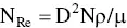
Because all units must cancel, it is best to use a consistent set of units. SI (Systeme Internationale) units work well. Normally, this is no problem, except for viscosity. Most of the time, viscosity is stated as cP. However, to use SI units, viscosity should be in units of kg/m‐s, also known as Pa‐s. Fortunately, the conversion is simple. 1 cP = 1 mPa‐s = 0.001 Pa‐s = 0.001 kg/m‐s. English units become very peculiar. If the lengths are in feet and the density is in lb/ft 3, with time in seconds, the viscosity unit to use is pound mass/foot‐second. The conversion from cP is 1 cP = 6.72 E‐4 pound mass/foot‐second. (I have yet to see a viscometer that reads in units of pound mass/foot‐second.)
For those who prefer to use inches, rpm, specific gravity, and cP, we can build in a conversion factor using those units:
(3.2) 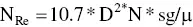
Caution: do not use the above expression without using the prescribed units!
Power Number
Power number is conceptually the ratio of power draw to impeller parameters, speed, and density. It is defined as:
(3.3) 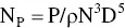
The main use of power number is to calculate power draw. It is a function of impeller type, Reynolds number, and various geometric factors. When using SI units, the power will be expressed in watts. If one chooses to use inches, rpm, Hp, and specific gravity, we can insert the conversion factor and rearrange for power:
(3.4) 
Same caution as for Eq. (3.2)
Note that power draw is quite sensitive to both impeller diameter and shaft speed.
Pumping Number
Pumping number is the ratio of impeller discharge rate (aka primary pumping capacity) to the cube of its diameter and the shaft speed:
Читать дальшеИнтервал:
Закладка:
Похожие книги на «Agitator Design for Gas-Liquid Fermenters and Bioreactors»
Представляем Вашему вниманию похожие книги на «Agitator Design for Gas-Liquid Fermenters and Bioreactors» списком для выбора. Мы отобрали схожую по названию и смыслу литературу в надежде предоставить читателям больше вариантов отыскать новые, интересные, ещё непрочитанные произведения.


Обсуждение, отзывы о книге «Agitator Design for Gas-Liquid Fermenters and Bioreactors» и просто собственные мнения читателей. Оставьте ваши комментарии, напишите, что Вы думаете о произведении, его смысле или главных героях. Укажите что конкретно понравилось, а что нет, и почему Вы так считаете.