Gregory T. Benz - Agitator Design for Gas-Liquid Fermenters and Bioreactors
Здесь есть возможность читать онлайн «Gregory T. Benz - Agitator Design for Gas-Liquid Fermenters and Bioreactors» — ознакомительный отрывок электронной книги совершенно бесплатно, а после прочтения отрывка купить полную версию. В некоторых случаях можно слушать аудио, скачать через торрент в формате fb2 и присутствует краткое содержание. Жанр: unrecognised, на английском языке. Описание произведения, (предисловие) а так же отзывы посетителей доступны на портале библиотеки ЛибКат.
- Название:Agitator Design for Gas-Liquid Fermenters and Bioreactors
- Автор:
- Жанр:
- Год:неизвестен
- ISBN:нет данных
- Рейтинг книги:4 / 5. Голосов: 1
-
Избранное:Добавить в избранное
- Отзывы:
-
Ваша оценка:
Agitator Design for Gas-Liquid Fermenters and Bioreactors: краткое содержание, описание и аннотация
Предлагаем к чтению аннотацию, описание, краткое содержание или предисловие (зависит от того, что написал сам автор книги «Agitator Design for Gas-Liquid Fermenters and Bioreactors»). Если вы не нашли необходимую информацию о книге — напишите в комментариях, мы постараемся отыскать её.
Agitator Design for Gas-Liquid Fermenters and Bioreactors — читать онлайн ознакомительный отрывок
Ниже представлен текст книги, разбитый по страницам. Система сохранения места последней прочитанной страницы, позволяет с удобством читать онлайн бесплатно книгу «Agitator Design for Gas-Liquid Fermenters and Bioreactors», без необходимости каждый раз заново искать на чём Вы остановились. Поставьте закладку, и сможете в любой момент перейти на страницу, на которой закончили чтение.
Интервал:
Закладка:
Some process results correlate well with simple physical measurements of agitation. For example, the ability to overcome density differences or viscosity ratios correlates well with characteristic fluid velocities [1]. However, many other process objectives do not correlate well with such simple measures. Examples of process results that have complex relationships to agitation and do not correlate well with pumping capacity, fluid velocity, or other simple measures would include blend time, mass transfer rate, heat transfer rate, off‐bottom solids suspension, solids suspension degree of uniformity, solids suspension cloud height, rate of particle attrition or shear damage, dissolved oxygen spatial distribution, reaction rate, reaction product distribution, and many others.
Since this book is about agitator design for fermenters/bioreactors, we will focus on the attributes of agitator design most important for those applications. The most important process result is normally the mass transfer rate (MTR), often called the OTR, or oxygen transfer rate, when oxygen is the species being transferred. This is generally the dominant design requirement.
The mass transfer rate depends on more than just agitation, of course. It also depends on the airflow, the properties of the broth, the organism’s ability to absorb the transferred gas (OUR, or oxygen uptake rate for aerobic systems), and a host of other factors. The principle agitation parameter for a given system is the power invested under gassed conditions. Therefore, the principle purposes of agitator design in this book are enumerated below and expanded upon in subsequent chapters. In most chapters, we will describe results based on the gas being oxygen. Chapter 11will delve into how to handle other gasses.
Provide sufficient power input to facilitate the required mass transfer rate. This will vary with tank geometry, scale of operation, pressure, temperature, allowable minimum dissolved gas concentration, and gas flowrate.
Use an impeller system designed to maximize fluid mixing and thereby minimize concentration gradients, while still dispersing gas.
Provide sufficient overall mixing. Usually, the agitation required to disperse gas is more than ample for other mixing requirements.
Optimization of power used. The same mass transfer rate can be achieved with different combinations of airflow and agitator power. The total power of agitator and compressor goes through a minimum. Ideally, the design should use that minimum unless other factors override this desire.
Optimization of capital cost. Within a certain design power, there is a range of acceptable agitator designs. But there can be differences in capital cost among different designs.
Optimization of total batch cycle energy costs. Since batch processes have different OTR requirements at different stages of the batch cycle, the power costs can be optimized at each stage, thereby minimizing total energy used per batch.
Optimization of total system economics. Tank geometry affects capital and energy costs of both the tank itself and the agitator
Assure the final design has the utmost in mechanical integrity. This includes the tank and the mounting arrangement. Historically, agitators for gas–liquid contacting have had higher mechanical failure rates than those used for simple liquid blending, yet the cost of downtime can be very high. We aim to remedy that by promoting design principles that lead to minimal downtime.
Choose vendors that not only build a good product, but can support it in the field.
References
1 1 Hicks, R.W., Morton, J.R., and Fenic, J.G. (1976). How to design agitators for desired process response. Chemical Engineering Magazine: 22–30.
2 2 Benz, G.T. (2007). The G‐value for agitator design: time to retire it? Chemical Engineering Progress 103: 43–47.
2 Major Steps in Successful Agitator Design
This chapter presents an overview of the main steps and logic required to achieve the best agitation system design. Subsequent chapters will provide more technical details and fundamental concepts so that each step can be undertaken. Figure 2.1provides a graphic summary of these steps. We will describe each one in more detail in the following paragraphs. The flow chart concept used here was inspired by the procedures in Ref. [1], but is expanded upon in more detail here specifically for bioreactor design.
Define Process Results
The first step in agitator design, or, for that matter, the design of any kind of process equipment, is to define the expected process result. For agitators, that could be a number of different things, such as degree of solids suspension, blend time to some specified degree of uniformity, characteristic fluid velocity, heat transfer coefficient, etc. While some or all of these process results may be needed or applicable to bioreactor design, in general, the requirement for a certain mass transfer rate is the most important and difficult to achieve. In other words, when an agitator is designed for mass transfer, the other process requirements are normally exceeded.
There are two exceptions to this. One is when the mass transfer requirement is very low (say, less than 10 mmol/l‐h). This is sometimes called micro‐aeration. In such a case, there may be minimum liquid velocities or blend time requirements. However, we feel that such cases are covered well in the general literature, such as in Refs. [1,2]. Therefore, we will not describe agitator design where velocity or blend time is the required results for low viscosity liquids. By “low viscosity,” we typically mean that the viscosity is less than 1000 cP. Viscosities less than 1000 cP typically have little effect on power draw or blending performance. However, heat transfer is affected at all viscosities, and mass transfer is affected when viscosity gets above approximately 50–80 cP.
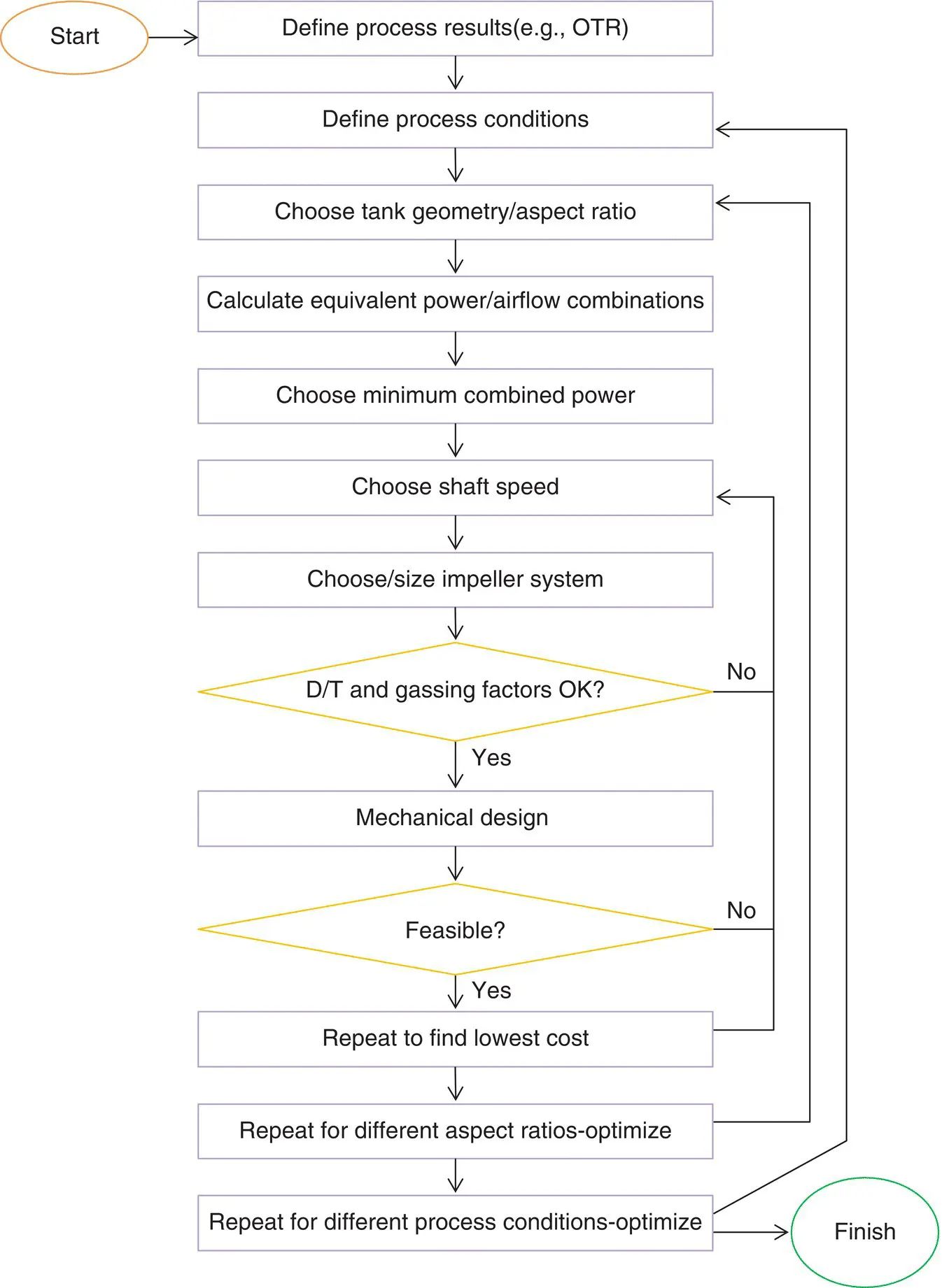
Figure 2.1 Agitator design flow chart.
The other exception is fermentation of highly viscous liquids, such as Xanthan gum or Gellan gum. At peak concentrations in the broth, such materials may have viscosities at a shear rate of 1 per second of 30 000 cP or even higher and apparent viscosities at the impeller of 2 000–10 000 cP. They are also quite non‐Newtonian. We will describe some viscosity models and effects in Chapter 3and specific issues with viscous fermenter design in Chapter 12.
With the foregoing in mind, the first step in our flow chart, defining process results, will focus on the required mass transfer rate, MTR. Since most fermenters consume oxygen, and the feed gas is air, most of this book will use aerobic fermentation with air feed for examples and calculations. So, we will usually refer to the mass transfer rate as the OTR, or oxygen transfer rate. Units are normally either mass per volume–time or moles per volume–time. The most common units of this type are mg/l‐h or mmol/l‐h. Relatively speaking, an “easy” fermentation would have an OTR of less than 100 mmol/l‐h, an “average” one would have around 150–200, and a difficult one would be 300 and up. There are huge implications on equipment size and power costs at these different levels.
Because mass transfer correlations are generally no more accurate than about ±30% when developed for the actual broth and can be much greater in error if generic, published correlations are used, the design OTR should be increased over the required OTR by a suitable factor.
Chapter 11will deal with cases where the feed gas is not air. For such cases, it may not be possible to optimize power the way we present it in this flow chart, as the cost of the feed gas is not just the power required to deliver it to the tank, and there may be other process constraints.
Читать дальшеИнтервал:
Закладка:
Похожие книги на «Agitator Design for Gas-Liquid Fermenters and Bioreactors»
Представляем Вашему вниманию похожие книги на «Agitator Design for Gas-Liquid Fermenters and Bioreactors» списком для выбора. Мы отобрали схожую по названию и смыслу литературу в надежде предоставить читателям больше вариантов отыскать новые, интересные, ещё непрочитанные произведения.


Обсуждение, отзывы о книге «Agitator Design for Gas-Liquid Fermenters and Bioreactors» и просто собственные мнения читателей. Оставьте ваши комментарии, напишите, что Вы думаете о произведении, его смысле или главных героях. Укажите что конкретно понравилось, а что нет, и почему Вы так считаете.