Gregory T. Benz - Agitator Design for Gas-Liquid Fermenters and Bioreactors
Здесь есть возможность читать онлайн «Gregory T. Benz - Agitator Design for Gas-Liquid Fermenters and Bioreactors» — ознакомительный отрывок электронной книги совершенно бесплатно, а после прочтения отрывка купить полную версию. В некоторых случаях можно слушать аудио, скачать через торрент в формате fb2 и присутствует краткое содержание. Жанр: unrecognised, на английском языке. Описание произведения, (предисловие) а так же отзывы посетителей доступны на портале библиотеки ЛибКат.
- Название:Agitator Design for Gas-Liquid Fermenters and Bioreactors
- Автор:
- Жанр:
- Год:неизвестен
- ISBN:нет данных
- Рейтинг книги:4 / 5. Голосов: 1
-
Избранное:Добавить в избранное
- Отзывы:
-
Ваша оценка:
Agitator Design for Gas-Liquid Fermenters and Bioreactors: краткое содержание, описание и аннотация
Предлагаем к чтению аннотацию, описание, краткое содержание или предисловие (зависит от того, что написал сам автор книги «Agitator Design for Gas-Liquid Fermenters and Bioreactors»). Если вы не нашли необходимую информацию о книге — напишите в комментариях, мы постараемся отыскать её.
Agitator Design for Gas-Liquid Fermenters and Bioreactors — читать онлайн ознакомительный отрывок
Ниже представлен текст книги, разбитый по страницам. Система сохранения места последней прочитанной страницы, позволяет с удобством читать онлайн бесплатно книгу «Agitator Design for Gas-Liquid Fermenters and Bioreactors», без необходимости каждый раз заново искать на чём Вы остановились. Поставьте закладку, и сможете в любой момент перейти на страницу, на которой закончили чтение.
Интервал:
Закладка:
Repeat for Different Aspect Ratios
All of the previous steps were within the confines of the starting aspect ratio. So, up to this point, hopefully we have an optimum design for that ratio. However, that ratio may not be optimum overall. So, ideally the entire process should be repeated over the range of aspect ratios that are not constrained by other factors, such as site restrictions and shop‐fabricated vs field‐fabricated issues. Only by doing this will we find the economically optimum design. The capex and opex of the agitator, vessel, and compressor should ideally be included.
Repeat for Different Process Conditions
All of the above was for the process conditions chosen at the start. But for some processes, these conditions can also be varied within limits. For example, the back pressure on the vessel can be varied, though there may be an upper limit, such as that required to allow exit of CO 2. But, for example, raising the pressure from 0 to 0.5 bar‐g may reduce agitator power requirements by 15–20%. Operating at a lower temperature increases oxygen solubility, reducing power but also reducing the metabolic processes within the organism. Lowering the peak cell population density can lower OUR but because the production rate will also be lowered, more total volumetric capacity will be required, albeit with a lower total power input. This is a classic case of capex vs opex. So, there are many potential options here.
Finish
When all of the steps are completed as many times as it takes to get the final optimum, the capex and opex per unit of capacity will be optimized. As you may have surmised, that is a lot of work. However, the savings could be quite significant. Moreover, a very experienced agitator designer can quickly go through the optimization for a given set of conditions and aspect ratio by instinctively avoiding designs that his experience indicates are poor or infeasible.
The balance of the book provides background information and details needed to complete these steps to the degree possible. Outside resources will be needed for cost data. The individual chapters are not organized as extensions of the step‐by‐step procedure, but, rather, as sources of information and calculation methods, as well as providing enough fundamental understanding to use the procedures described herein.
Summary of Chapter
This chapter has presented a series of steps to arrive at optimum fermenter design and operation. All of these steps will be covered in this book, in varying degrees of detail. The book will not follow this logic chapter by chapter, as a lot of background information and principles must be established before optimization can begin. The next several chapters will do that. The optimization steps begin in Chapter 8. There will also be several chapters after those covering optimization that will deal with special issues such as heat transfer, aspect ratio, and viscous fermentation. Sorry if this summary seems a bit repetitively redundant after the section “ Finish.”
List of Symbols
CPHeat capacity at constant pressureDImpeller diameterkThermal conductivityTTank diameterZLiquid height
References
1 1 Hicks, R.W., Morton, J.R., and Fenic, J.G. (1976). How to design agitators for desired process response. Chemical Engineering Magazine: 22–30.
2 2 Fasano, J.B., Bakker, A., and Penney, W.R. (1994). Advanced impeller geometry boosts liquid agitation. Chemical Engineering 7 pages.
3 Agitator Fundamentals
Before delving into details of agitation specific to bioreactors, we must establish a common framework of terminology and principles common to all agitation systems. This chapter will cover basic terminology, how experimental data are usually correlated, and some basic viscosity models used in fermentation broths.
Agitated Tank Terminology
A very simplified view of an agitated tank may be found in Figure 3.1. Though simplified, all of the main elements of an agitator and tank may be seen there. A schematic view with components labeled and a few major nomenclature symbols may be found in Figure 3.2.
An agitated tank consists of a number of elements and is dimensionally described by a number of symbols. We will go through these more or less in the order of power flow, referring to the nomenclature of Figure 3.2.
Prime Mover
Motive energy is provided to an agitator by means of a prime mover, which provides power in a rotary fashion. Usually, it is an electric motor, as shown in Figure 3.2. For fermenters, a variable speed drive is often provided, usually by means of a variable frequency drive (VFD), though other technologies are possible. In principle, many other rotary power sources could be used. Some that the author has seen used include air motors, DC motors, hydraulic motors, and even diesel engines. But, probably more than 99% of the time, the prime mover will be an electric motor.

Figure 3.1 Agitated tank.
Source: Photo courtesy Chemineer, a brand of NOV. Permission granted by NOV.
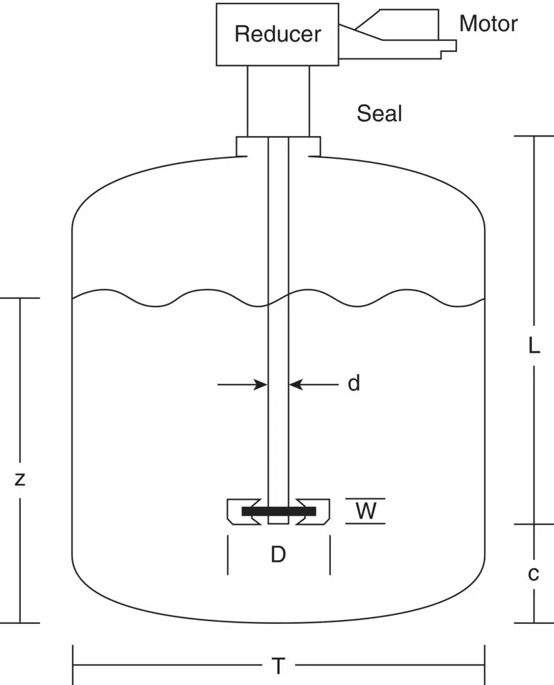
Figure 3.2 Agitated tank sketch.
Reducer
Most agitator designs do not operate at direct motor speed, except in very small tanks. The reducer decreases the shaft speed below motor speed and increases torque. In most agitator designs, the reducer must also support the weight of the shaft and impellers, the thrust due to tank pressure or vacuum, and the bending moment created by random fluid forces acting on the impellers. In some cases, those forces are supported by a separate set of bearings, and the shaft is flexibly coupled to the reducer.
The two most common reducer designs in industry are belt drive and gear drive. Most fermenter agitators use gear drives. More discussion of drive types will be found in Chapter 17.
Shaft Seal
Although not all agitators have shaft seals (some are mounted on open‐top tanks or basins), those used in fermenters almost always do. The purpose of the seal, in addition to maintaining tank pressure or vacuum, is to isolate tank contents from the outside environment. This may be done to keep foreign matter from contaminating the broth or to protect plant personnel from exposure to potentially harmful organisms or gases. Often, the shaft seal area is heated to create a sterile barrier. More information on shaft seals will be found in Chapter 15.
Wetted Parts
The power and torque from the reducer are transmitted to the tank contents by means of a shaft with diameter d, extending a distance L from the mounting flange. On the shaft are mounted one or more impellers of diameter D and actual blade width or height, W, located off bottom at a distance C. For this book, we measure C from the bottom edge of the impeller. Some other sources use the centerline of the impeller. We also define D as the flat‐to‐flat dimension of the blades in plan view, rather than the swept circle, called D S. This makes a difference of about 1% in the calculated diameter for a pitched blade turbine of standard design, for example. This is illustrated in Figure 3.3, along with a few other relevant dimensions, such as the blade thickness, t b.
For multiple impellers, we would use subscripts such as D 1, D 2, C 1, and C 2.
Читать дальшеИнтервал:
Закладка:
Похожие книги на «Agitator Design for Gas-Liquid Fermenters and Bioreactors»
Представляем Вашему вниманию похожие книги на «Agitator Design for Gas-Liquid Fermenters and Bioreactors» списком для выбора. Мы отобрали схожую по названию и смыслу литературу в надежде предоставить читателям больше вариантов отыскать новые, интересные, ещё непрочитанные произведения.


Обсуждение, отзывы о книге «Agitator Design for Gas-Liquid Fermenters and Bioreactors» и просто собственные мнения читателей. Оставьте ваши комментарии, напишите, что Вы думаете о произведении, его смысле или главных героях. Укажите что конкретно понравилось, а что нет, и почему Вы так считаете.