Gregory T. Benz - Agitator Design for Gas-Liquid Fermenters and Bioreactors
Здесь есть возможность читать онлайн «Gregory T. Benz - Agitator Design for Gas-Liquid Fermenters and Bioreactors» — ознакомительный отрывок электронной книги совершенно бесплатно, а после прочтения отрывка купить полную версию. В некоторых случаях можно слушать аудио, скачать через торрент в формате fb2 и присутствует краткое содержание. Жанр: unrecognised, на английском языке. Описание произведения, (предисловие) а так же отзывы посетителей доступны на портале библиотеки ЛибКат.

- Название:Agitator Design for Gas-Liquid Fermenters and Bioreactors
- Автор:
- Жанр:
- Год:неизвестен
- ISBN:нет данных
- Рейтинг книги:4 / 5. Голосов: 1
-
Избранное:Добавить в избранное
- Отзывы:
-
Ваша оценка:
Agitator Design for Gas-Liquid Fermenters and Bioreactors: краткое содержание, описание и аннотация
Предлагаем к чтению аннотацию, описание, краткое содержание или предисловие (зависит от того, что написал сам автор книги «Agitator Design for Gas-Liquid Fermenters and Bioreactors»). Если вы не нашли необходимую информацию о книге — напишите в комментариях, мы постараемся отыскать её.
Agitator Design for Gas-Liquid Fermenters and Bioreactors — читать онлайн ознакомительный отрывок
Ниже представлен текст книги, разбитый по страницам. Система сохранения места последней прочитанной страницы, позволяет с удобством читать онлайн бесплатно книгу «Agitator Design for Gas-Liquid Fermenters and Bioreactors», без необходимости каждый раз заново искать на чём Вы остановились. Поставьте закладку, и сможете в любой момент перейти на страницу, на которой закончили чтение.
Интервал:
Закладка:
Greek letters
θBlade angle from a horizontal planeτBlend timeμDynamic viscosityμaApparent viscosityρFluid densityσsShear stressσyYield stressγShear rate; dv/dx
References
Because the descriptions and use of dimensionless numbers in this chapter are found in many references, we chose not to do a line by line reference. Instead, one can find an introduction to these concepts in the references below, among others.
1 1 Dickey, D.D. and Fenic, J.G. (1976). Dimensional analysis for fluid agitation systems. Chemical Engineering Magazine: 7–13.
2 2 Paul, E. et al. (eds.) (2004). Handbook of Industrial Mixing. Various authors. Wiley Interscience (Look up by the name of the dimensionless number).
4 Agitator Behavior under Gassed Conditions
When an agitator is operated under gassed conditions (whether the gas is added or evolving from the process), it behaves differently from operating in liquid only. The presence of gas, in addition to possibly influencing mass transfer when the gas and liquid are not in equilibrium, can create several important effects. Among those are flooding of the impeller versus dispersing the gas, power draw effects, entrained gas, or holdup in the liquid and mechanical effects. We will go through each of these in turn, as well as the issue of what happens when there is a variable gas flowrate.
The above behaviors are mainly correlated by three dimensionless number groups: Reynolds number, Froude number, and Gassing factor. A fourth group, known as the dimensionless hydraulic force, is used for mechanical design and will be used in examples in Chapter 16.
Flooding
Flooding is a condition in which there is too much gas flowing into an impeller for it to effectively disperse it. If the main purpose of the agitator is to disperse the gas, this is obviously not a desirable condition. But how do we define it quantitatively and how do we measure it? There are actually several ways. We will describe three of them here.
k la Method
By k la, we mean the overall mass transfer coefficient, as defined by:
(4.1) 
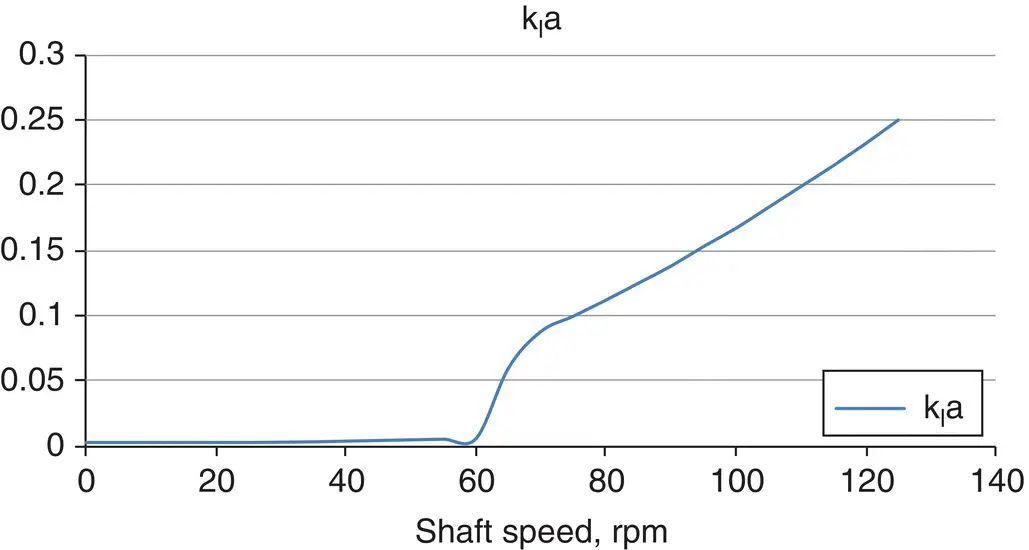
Figure 4.1 Flooding determination by using k la.
Imagine an agitator operating at zero rpm, with gas being bubbled below the impeller. Although the impeller is not dispersing gas, there will still be some mass transfer possible, and therefore, the value of k la will be non‐zero. As the shaft speed increases, the k la value will remain essentially constant, until a certain threshold speed is reached, at which point the k la value will start increasing rapidly, as shown in Figure 4.1. We would call that threshold speed the flooding emergence point, by one definition. By inspection of Figure 4.1, the flooding emergence point is about 58 rpm.
One could also use mass transfer rate as the y‐axis if the driving force remained constant.
While this definition of flooding has the advantage of clearly defining the point at which the agitator actually begins to influence mass transfer and thus relates to the main purpose for the use of the agitator, it is experimentally difficult to carry out. Most published definitions and correlations of flooding do not use this method, as we will see. This method does, however, have the advantage of being possible to carry out in an opaque vessel.
Power Draw Method
When gas is introduced into an impeller, it lowers power consumption, as will be described later in more detail. However, in many cases, the power draw increases when flooding, especially for Rushton or other impellers with flat vertical blades. This is due to the loss of gas pockets which streamline flow, illustrated in Chapter 5. This can be used as an indication of flooding, as illustrated in Figure 4.2
However, this phenomenon does not occur at all Froude numbers and can be difficult to detect for deeply concave impellers, as they have little or no gas pockets to streamline flow. For such impellers, the gassing factor is mostly a density reduction factor, which might not change much due to flooding. An opaque vessel will work for this method also.
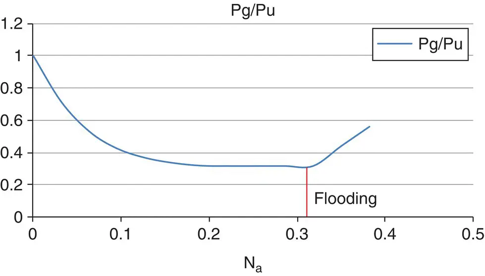
Figure 4.2 Impeller flooding by power draw.
Visual Flow Pattern Method
The most common method of defining and determining flooding is the visual method. It is the method upon which all flooding equations in this book are based. Referring to Figure 4.3, flooding emergence occurs when the bubble flow and dispersion pattern changes from condition (a) to condition (b). This is easily observed in a transparent vessel and is a very repeatable condition. In condition (b), the bubbles are driven to the vessel wall, more or less in the plane of the impeller. This a somewhat conservative definition of flooding, as mass transfer enhancement actually begins before the bubbles are fully driven to the wall. It actually begins when the bubbles are driven even a short distance off a vertical path, as long as the impeller Froude number is at least 0.03 for Rushton turbines (the minimum Froude number may be somewhat lower for concave and deeply concave impellers, but the author is unaware of studies conducted below a Froude number of 0.03.)
Condition (c) in Figure 4.3is called complete dispersion. It occurs when gas is driven to the bottom of the tank and some of it is recirculated into the impeller. It is not a design condition per se, but usually occurs when agitation is sufficient to support medium and high mass transfer rates (for example, above 80 mmol/l‐h for an air‐based fermentation at a back pressure of 1 bar‐g or less.)
The transitions from condition (a) through condition (c) can be thought of as either increasing shaft speed at constant airflow or decreasing airflow at constant shaft speed.
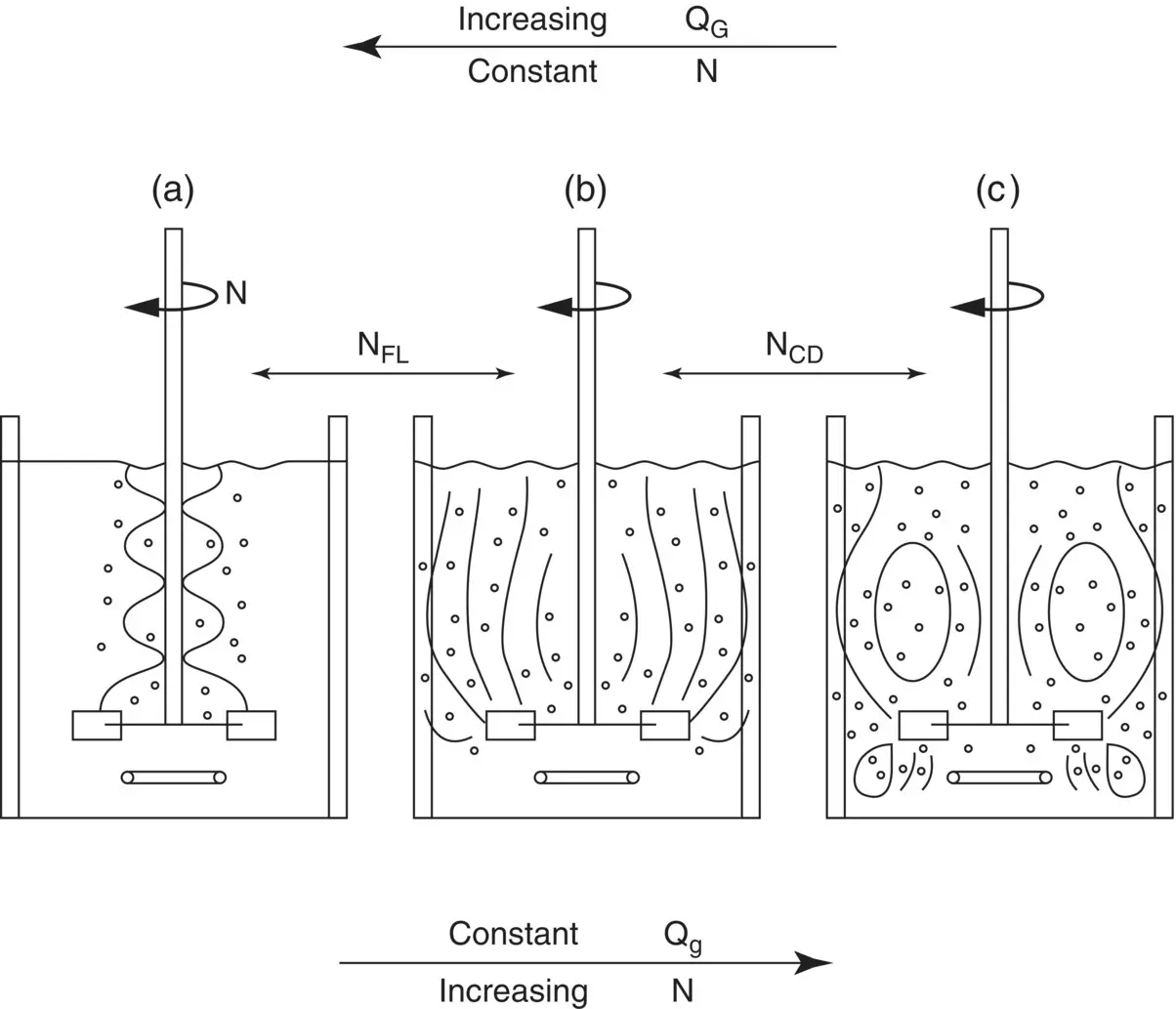
Figure 4.3 Visual flooding.
The above definitions work well for radial flow impellers, which are most commonly used as the primary disperser. Some systems use only axial flow impellers. There is no standard definition of flooding for these. The k la method could be used, whether the impellers are up or down pumping. It would be difficult to use the visual method for an up‐pumping system. For down pumping, there is a transition from direct loading (the gas goes through the impeller on the way up) to indirect loading (the gas is driven out of the impeller’s path by its discharge velocity, and some gas is recirculated into the impeller from above). We do not have a figure to illustrate this. But this transition could be a sort of flooding definition.
Effect on Power Draw
As mentioned in the first section on flooding, when gas is introduced to a liquid, it affects power draw. At very low gas rates, some impellers actually have an increased power draw. Likely, this is due to increasing the discharge head imposed on the impeller. But at most gas flowrates used in fermenters and bioreactors, gas causes the power to drop.
Читать дальшеИнтервал:
Закладка:
Похожие книги на «Agitator Design for Gas-Liquid Fermenters and Bioreactors»
Представляем Вашему вниманию похожие книги на «Agitator Design for Gas-Liquid Fermenters and Bioreactors» списком для выбора. Мы отобрали схожую по названию и смыслу литературу в надежде предоставить читателям больше вариантов отыскать новые, интересные, ещё непрочитанные произведения.


Обсуждение, отзывы о книге «Agitator Design for Gas-Liquid Fermenters and Bioreactors» и просто собственные мнения читателей. Оставьте ваши комментарии, напишите, что Вы думаете о произведении, его смысле или главных героях. Укажите что конкретно понравилось, а что нет, и почему Вы так считаете.