Caner Ozdemir - Inverse Synthetic Aperture Radar Imaging With MATLAB Algorithms
Здесь есть возможность читать онлайн «Caner Ozdemir - Inverse Synthetic Aperture Radar Imaging With MATLAB Algorithms» — ознакомительный отрывок электронной книги совершенно бесплатно, а после прочтения отрывка купить полную версию. В некоторых случаях можно слушать аудио, скачать через торрент в формате fb2 и присутствует краткое содержание. Жанр: unrecognised, на английском языке. Описание произведения, (предисловие) а так же отзывы посетителей доступны на портале библиотеки ЛибКат.
- Название:Inverse Synthetic Aperture Radar Imaging With MATLAB Algorithms
- Автор:
- Жанр:
- Год:неизвестен
- ISBN:нет данных
- Рейтинг книги:5 / 5. Голосов: 1
-
Избранное:Добавить в избранное
- Отзывы:
-
Ваша оценка:
Inverse Synthetic Aperture Radar Imaging With MATLAB Algorithms: краткое содержание, описание и аннотация
Предлагаем к чтению аннотацию, описание, краткое содержание или предисловие (зависит от того, что написал сам автор книги «Inverse Synthetic Aperture Radar Imaging With MATLAB Algorithms»). Если вы не нашли необходимую информацию о книге — напишите в комментариях, мы постараемся отыскать её.
covers in greater detail the fundamental and advanced topics necessary for a complete understanding of inverse synthetic aperture radar (ISAR) imaging and its concepts. Distinguished author and academician, Caner Özdemir, describes the practical aspects of ISAR imaging and presents illustrative examples of the radar signal processing algorithms used for ISAR imaging. The topics in each chapter are supplemented with MATLAB codes to assist readers in better understanding each of the principles discussed within the book.
This new edition incudes discussions of the most up-to-date topics to arise in the field of ISAR imaging and ISAR hardware design. The book provides a comprehensive analysis of advanced techniques like Fourier-based radar imaging algorithms, and motion compensation techniques along with radar fundamentals for readers new to the subject.
The author covers a wide variety of topics, including:
Radar fundamentals, including concepts like radar cross section, maximum detectable range, frequency modulated continuous wave, and doppler frequency and pulsed radar The theoretical and practical aspects of signal processing algorithms used in ISAR imaging The numeric implementation of all necessary algorithms in MATLAB ISAR hardware, emerging topics on SAR/ISAR focusing algorithms such as bistatic ISAR imaging, polarimetric ISAR imaging, and near-field ISAR imaging, Applications of SAR/ISAR imaging techniques to other radar imaging problems such as thru-the-wall radar imaging and ground-penetrating radar imaging Perfect for graduate students in the fields of electrical and electronics engineering, electromagnetism, imaging radar, and physics,
also belongs on the bookshelves of practicing researchers in the related areas looking for a useful resource to assist them in their day-to-day professional work.
Inverse Synthetic Aperture Radar Imaging With MATLAB Algorithms — читать онлайн ознакомительный отрывок
Ниже представлен текст книги, разбитый по страницам. Система сохранения места последней прочитанной страницы, позволяет с удобством читать онлайн бесплатно книгу «Inverse Synthetic Aperture Radar Imaging With MATLAB Algorithms», без необходимости каждый раз заново искать на чём Вы остановились. Поставьте закладку, и сможете в любой момент перейти на страницу, на которой закончили чтение.
Интервал:
Закладка:
The RCS area of a target does not necessarily bear a direct link with the physical cross‐sectional area of that target but depends on other parameters as well. Besides the aperture of the target seen by the radar (or projected cross section), the EM reflectivity characteristics of the target's surface and the directivity of the radar reflection caused by the target's geometric shape are the key parameters that affect the RCS value. Therefore, RCS can be approximated as the multiplication of (i) projected cross section, S ; (ii) reflectivity, Γ ; and (iii) directivity, D as
(2.12) 
Here, projected cross section is the cross‐sectional area of the object along the radar look‐angle direction. This gives the projected area of the illuminated region of the object by the incident wave. Reflectivity of the target gives the amount (percentage) of the intercepted and reradiated EM energy by the target. Directivity is the ratio of scattered energy in the radar direction to the scattered energy from an isotropic scatterer (such that this isotropic scattering is uniform in all directions).
The value of RCS can be stated in different polarization of the incoming and outgoing EM wave. If the radar is transmitting in vertical ( V ) polarization, vertically polarized scattered energy is used for the determination of RCS. Similarly, if the radar is transmitting in horizontal ( H ) polarization, horizontally polarized scattered energy should be used for the calculation of RCS. The term SCS refers to all types of polarization for transmission and reception. Therefore, SCS presents the all possible polarization types, such as V – V , V – H , H – V , and H – H where the first letter is used for the transmitted and the second term is used for the received polarization of the EM wave and also for RCS.
It is essential to point out that the RCS of an object is both angle dependent and frequency dependent. As the look angle toward a target changes, the projected cross section of that target generally changes. Depending on the structure and the material of the target, the reflectivity of the target might also change. Overall, the RCS of the target alters as the look angle varies. Similarly, if the frequency of the EM wave changes, the effective electrical size (or projected cross section) of the target changes as well. Furthermore, the EM reflectivity is also a frequency‐dependent quantity; therefore, the RCS of the target also varies as the frequency of the radar changes. Consequently, an RCS of an object is characterized together with the look angle and the particular frequency of operation. It is also important to note that RCS is independent of the target's distance from the radar. Therefore, the RCS of an object at different range distances is exactly the same.
2.3.2 RCS of Simple‐Shaped Objects
RCS calculation of simply shaped objects can be approximated with simple analytical expressions. There has been a lot of interest in formulating the scattered field and the RCS from simple objects such as a sphere, cylinder, ellipsoid, or plate. Since the RCS analyses of such objects are very well documented (Crispin and Siegel 1970; Ruck et al. 1970; Skolnik 1990, Warnick and Chew 1999; Sullivan 2000), only some of them (those that are important in radar imaging) are listed in Figure 2.4. When usual targets such as airplanes, ships, and tanks are considered, their physical shapes include canonical structures such as corner reflectors, cylinder‐like formations, and flat and curved surfaces. Therefore, the knowledge of RCS from basic canonical shapes is important to comprehend the RCS contribution of these substructures on the target to the total RCS.
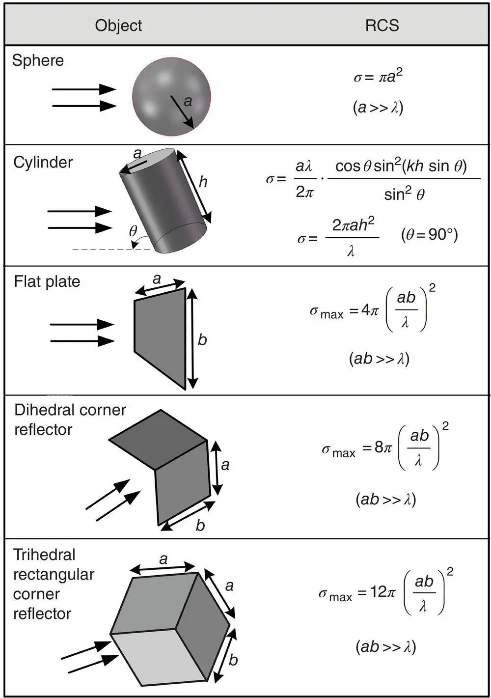
Figure 2.4 RCS values for perfectly conducting simple objects (all objects are taken as perfect electrical conductors).
2.3.3 RCS of Complex‐Shaped Objects
As given in Figure 2.4, the calculation of canonical‐shaped objects can be analytically approximately formulated. On the other hand, RCS calculation or prediction of complexly shaped objects is usually a difficult task. There exist some numerical approaches by which to estimate the RCS from arbitrarily shaped object. Some full‐wave approaches based on electric field integral equation (EFIE) or magnetic field integral equation (MFIE) techniques (Balanis 1982; Ergül and Gürel 2005) are used to calculate the scattering from electrically small targets. The common numerical technique used to implement such approaches is the well‐known method of moment (MoM) (Ekelman and Thiele 1980) technique. MoM‐based techniques are computationally effective when the electrical size of the target is on the order of, at most, a few wavelengths. At high frequencies when the size of the scatterer is much greater than the wavelength, however, the computation burden of MoM becomes problematic such that the computation time and the computation memory requirements are not manageable in simulating the scattering from electrically large and complex targets such as tanks, airplanes, and ships.
To cope with such targets whose electrical length is more than tens of wavelength, some asymptotic or hybrid methods (Kim and Thiele 1982; Ling et al. 1989) that combine different EM techniques in one simulator are used. The most famous one is called the shooting and bouncing ray (SBR) technique that can successfully estimate the scattering from large and complex platforms at high frequencies (Bhalla and Ling 1993, 1995). The SBR technique efficiently combines the geometric optics (GO) and the PO approaches (Knott 1993; Knott et al. 2004) to get the accurate estimation of the scattering (or the RCS) from large and complex objects at high frequencies and beyond (Ling et al. 1989; Weinmann 2006; Özdemir et al. 2014; Kırık and Özdemir 2019). An example of an RCS calculation from a complex airplane model is shown in Figure 2.5where the RCS of a 14 m long airplane model is used for the simulation of the monostatic RCS. The calculation is done for the whole azimuth angles at the operating frequency of 2 GHz.
2.4 Radar Range Equation
The main goal of a typical radar is to detect the scattered (or backscattered) EM echoes from a target and to extract the information within those EM signatures. The following sequential events happen as the EM wave travels from the transmitter to the receiver:
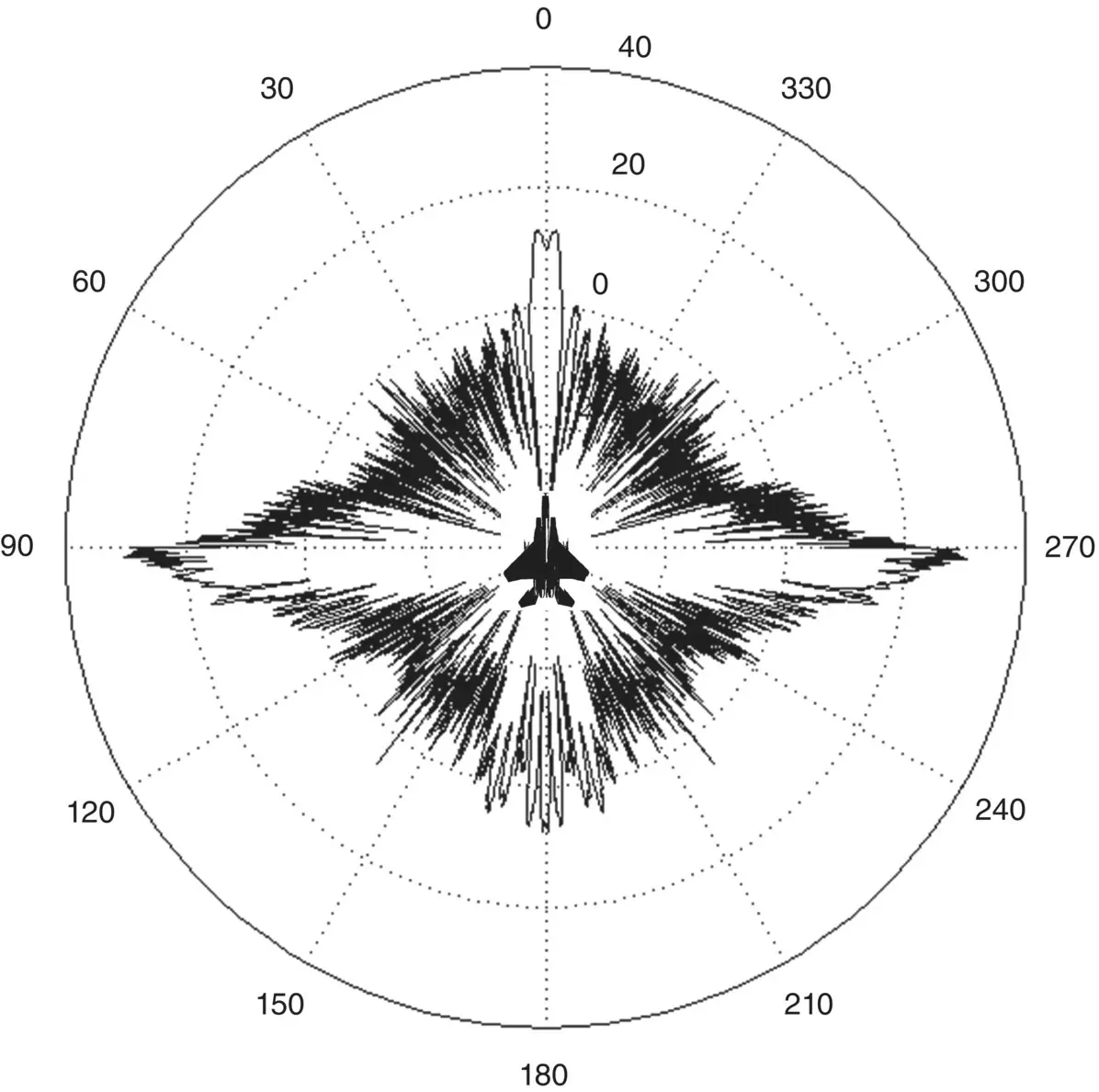
Figure 2.5 Simulated RCS (in dBsm) of an aircraft model at 2 GHz as a function of azimuth angles.
1 First, the radar signal is generated with the help of the microwave generator (or source).
2 Then the generated signal is transferred to the transmitter by means of transmission lines.
3 The signal is sent out via the transmitting antenna.
4 The radar wave travels in the air and reaches the target.
5 Only some little portion of the transmitted radar signal is captured by the target and reflected back depending on the RCS value of the target.
6 The reflected wave travels in the air, and only a small fraction of the reflected energy reaches back to the radar receiver.
7 The receiver antenna captures some portion of this energy and passes it to the radar receiver.
Читать дальшеИнтервал:
Закладка:
Похожие книги на «Inverse Synthetic Aperture Radar Imaging With MATLAB Algorithms»
Представляем Вашему вниманию похожие книги на «Inverse Synthetic Aperture Radar Imaging With MATLAB Algorithms» списком для выбора. Мы отобрали схожую по названию и смыслу литературу в надежде предоставить читателям больше вариантов отыскать новые, интересные, ещё непрочитанные произведения.


Обсуждение, отзывы о книге «Inverse Synthetic Aperture Radar Imaging With MATLAB Algorithms» и просто собственные мнения читателей. Оставьте ваши комментарии, напишите, что Вы думаете о произведении, его смысле или главных героях. Укажите что конкретно понравилось, а что нет, и почему Вы так считаете.