Jakob J. Zyl - Introduction to the Physics and Techniques of Remote Sensing
Здесь есть возможность читать онлайн «Jakob J. Zyl - Introduction to the Physics and Techniques of Remote Sensing» — ознакомительный отрывок электронной книги совершенно бесплатно, а после прочтения отрывка купить полную версию. В некоторых случаях можно слушать аудио, скачать через торрент в формате fb2 и присутствует краткое содержание. Жанр: unrecognised, на английском языке. Описание произведения, (предисловие) а так же отзывы посетителей доступны на портале библиотеки ЛибКат.
- Название:Introduction to the Physics and Techniques of Remote Sensing
- Автор:
- Жанр:
- Год:неизвестен
- ISBN:нет данных
- Рейтинг книги:3 / 5. Голосов: 1
-
Избранное:Добавить в избранное
- Отзывы:
-
Ваша оценка:
Introduction to the Physics and Techniques of Remote Sensing: краткое содержание, описание и аннотация
Предлагаем к чтению аннотацию, описание, краткое содержание или предисловие (зависит от того, что написал сам автор книги «Introduction to the Physics and Techniques of Remote Sensing»). Если вы не нашли необходимую информацию о книге — напишите в комментариях, мы постараемся отыскать её.
delivers a comprehensive update to the authoritative textbook, offering readers new sections on radar interferometry, radar stereo, and planetary radar. It explores new techniques in imaging spectroscopy and large optics used in Earth orbiting, planetary, and astrophysics missions. It also describes remote sensing instruments on, as well as data acquired with, the most recent Earth and space missions.
Readers will benefit from the brand new and up-to-date concept examples and full-color photography, 50% of which is new to the series. You’ll learn about the basic physics of wave/matter interactions, techniques of remote sensing across the electromagnetic spectrum (from ultraviolet to microwave), and the concepts behind the remote sensing techniques used today and those planned for the future.
The book also discusses the applications of remote sensing for a wide variety of earth and planetary atmosphere and surface sciences, like geology, oceanography, resource observation, atmospheric sciences, and ionospheric studies. This new edition also incorporates:
A fulsome introduction to the nature and properties of electromagnetic waves An exploration of sensing solid surfaces in the visible and near infrared spectrums, as well as thermal infrared, microwave, and radio frequencies A treatment of ocean surface sensing, including ocean surface imaging and the mapping of ocean topography A discussion of the basic principles of atmospheric sensing and radiative transfer, including the radiative transfer equation Perfect for senior undergraduate and graduate students in the field of remote sensing instrument development, data analysis, and data utilization,
will also earn a place in the libraries of students, faculty, researchers, engineers, and practitioners in fields like aerospace, electrical engineering, and astronomy.
Introduction to the Physics and Techniques of Remote Sensing — читать онлайн ознакомительный отрывок
Ниже представлен текст книги, разбитый по страницам. Система сохранения места последней прочитанной страницы, позволяет с удобством читать онлайн бесплатно книгу «Introduction to the Physics and Techniques of Remote Sensing», без необходимости каждый раз заново искать на чём Вы остановились. Поставьте закладку, и сможете в любой момент перейти на страницу, на которой закончили чтение.
Интервал:
Закладка:
In homogeneous, isotropic, and nonmagnetic media, Maxwell’s equations can be combined to derive the wave equation:
(2.7) 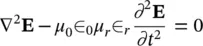
where ∇ 2is the Laplacian. In the case of a sinusoidal field:
(2.8) 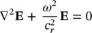
where
(2.9) 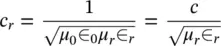
Usually μ r= 1 and ∈ rvaries from 1 to 80 and is a function of the frequency. The solution for the above differential equation is given by:
(2.10) 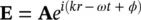
where Ais the wave amplitude, ω is the angular frequency, ϕ is the phase, and k is the wave vector in the propagation medium (  speed of light in vacuum). The wave frequency ν is defined as ν = ω /2 π .
Remote sensing instruments exploit different aspects of the solution to the wave equation in order to learn more about the properties of the medium from which the radiation is being sensed. For example, the interaction of electromagnetic waves with natural surfaces and atmospheres is strongly dependent on the frequency of the waves. This will manifest itself in changes in the amplitude (the magnitude of Ain (2.10)) of the received wave as the frequency of the observation is changed. This type of information is recorded by multispectral instruments such as the LandSat Thematic Mapper and the Advanced Spaceborne Thermal Emission and Reflection Radiometer. In other cases, one can infer information about the electrical properties and geometry of the surface by observing the polarization (the vector components of Ain (2.10)) of the received waves. This type of information is recorded by polarimeters and polarimetric radars. Doppler lidars and radars, on the other hand, measure the change in frequency between the transmitted and received waves in order to infer the velocity with which an object or medium is moving. This information is contained in the angular frequency ω of the wave shown in (2.10). The quantity kr − ωt + φ in (2.10)is known as the phase of the wave. This phase changes by 2 π every time the wave moves through a distance equal to the wavelength λ . Measuring the phase of a wave therefore provides an extremely accurate way to measure the distance that the wave actually travelled. Interferometers exploit this property of the wave to accurately measure differences in the path length between a source and two collectors, allowing one to significantly increase the resolution with which the position of the source can be established or to measure slight displacements.
2.1.4 Quantum Properties of Electromagnetic Radiation
Maxwell’s formulation of electromagnetic radiation leads to a mathematically smooth wave motion of fields. However, at very short wavelengths, it fails to account for certain significant phenomena when the wave interacts with matter. In this case a quantum description is more appropriate.
The electromagnetic energy can be presented in a quantized form as bursts of radiation with a quantized radiant energy Q , which is proportional to the frequency ν :
(2.11) 
where h = Planck’s constant = 6.626 × 10 −34joule second. The radiant energy carried by the wave is not delivered to a receiver as if it is spread evenly over the wave, as Maxwell had visualized, but is delivered on a probabilistic basis. The probability that a wave train will make full delivery of its radiant energy at some place along the wave is proportional to the flux density of the wave at that place. If a very large number of wave trains are coexistent, then the overall average effect follows Maxwell’s equations.
2.1.5 Polarization
An electromagnetic wave consists of a coupled electric and magnetic force field. In free space, these two fields are at right angles to each other and transverse to the direction of propagation. The direction and magnitude of only one of the fields (usually the electric field) is sufficient to completely specify the direction and magnitude of the other field using Maxwell’s equations.
The polarization of the electromagnetic wave is contained in the elements of the vector amplitude Aof the electric field in Equation (2.10). For a transverse electromagnetic wave, this vector is orthogonal to the direction in which the wave is propagating, and therefore we can completely describe the amplitude of the electric field by writing Aas a two‐dimensional complex vector:
(2.12) 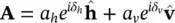
Here we denote the two orthogonal basis vectors as  for horizontal and
  for vertical . Horizontal polarization is usually defined as the state where the electric vector is perpendicular to the plane of incidence. Vertical polarization is orthogonal to both horizontal polarization and the direction of propagation, and corresponds to the case where the electric vector is in the plane of incidence. Any two orthogonal basis vectors could be used to describe the polarization, and in some cases the right‐ and left‐handed circular basis is used. The amplitudes, a hand a v, and the relative phases, δ hand δ v, are real numbers. The polarization of the wave can be thought of as that figure that the tip of the electric field would trace over time at a fixed point in space. Taking the real part of (2.12), we find that the polarization figure is the locus of all the points in the h‐v plane that have the coordinates E h= a hcos δ h; E v= a vcos δ v. It can easily be shown that the points on the locus satisfy the expression
(2.13) 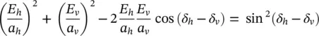
This is the expression of an ellipse, shown in Figure 2.2. Therefore, in the general case, electromagnetic waves are elliptically polarized. In tracing the ellipse, the tip of the electric field can rotate either clockwise or counterclockwise; this direction is denoted by the handedness of the polarization. The definition of handedness accepted by the Institute for Electrical and Electronics Engineers, IEEE, is that a wave is said to have right‐handed polarization if the tip of the electric field vector rotates clockwise when the wave is viewed receding from the observer. If the tip of the electric field vector rotates counterclockwise when the wave is viewed in the same way, it has a left‐handed polarization. It is worth pointing out that in the optical literature a different definition of handedness is often encountered. In that case, a wave is said to have right‐handed (left‐handed) polarization when the wave is viewed approaching the observer, and tip of the electric field vector rotates in the clockwise (counterclockwise) direction.
Читать дальшеИнтервал:
Закладка:
Похожие книги на «Introduction to the Physics and Techniques of Remote Sensing»
Представляем Вашему вниманию похожие книги на «Introduction to the Physics and Techniques of Remote Sensing» списком для выбора. Мы отобрали схожую по названию и смыслу литературу в надежде предоставить читателям больше вариантов отыскать новые, интересные, ещё непрочитанные произведения.


Обсуждение, отзывы о книге «Introduction to the Physics and Techniques of Remote Sensing» и просто собственные мнения читателей. Оставьте ваши комментарии, напишите, что Вы думаете о произведении, его смысле или главных героях. Укажите что конкретно понравилось, а что нет, и почему Вы так считаете.