Doug Lowe - Networking All-in-One For Dummies
Здесь есть возможность читать онлайн «Doug Lowe - Networking All-in-One For Dummies» — ознакомительный отрывок электронной книги совершенно бесплатно, а после прочтения отрывка купить полную версию. В некоторых случаях можно слушать аудио, скачать через торрент в формате fb2 и присутствует краткое содержание. Жанр: unrecognised, на английском языке. Описание произведения, (предисловие) а так же отзывы посетителей доступны на портале библиотеки ЛибКат.
- Название:Networking All-in-One For Dummies
- Автор:
- Жанр:
- Год:неизвестен
- ISBN:нет данных
- Рейтинг книги:4 / 5. Голосов: 1
-
Избранное:Добавить в избранное
- Отзывы:
-
Ваша оценка:
Networking All-in-One For Dummies: краткое содержание, описание и аннотация
Предлагаем к чтению аннотацию, описание, краткое содержание или предисловие (зависит от того, что написал сам автор книги «Networking All-in-One For Dummies»). Если вы не нашли необходимую информацию о книге — напишите в комментариях, мы постараемся отыскать её.
s covers all the basic and not-so-basic information you need to get a network up and running. It also helps you keep it running as it grows more complicated, develops bugs, and encounters all the fun sorts of trouble you expect from a complex system. Ideal both as a starter for newbie administrators and as a handy quick reference for pros, this book is built for speed, allowing you to get past all the basics—like installing and configuring hardware and software, planning your network design, and managing cloud services—so you can get on with what your network is actually intended to do.
In a friendly, jargon-free style, Doug Lowe—an experienced IT Director and prolific tech author—covers the essential, up-to-date information for networking in systems such as Linux and Windows 10 and clues you in on best practices for security, mobile, and more. Each of the nine minibooks demystifies the basics of one key area of network management.
Plan and administrate your network Implement virtualization Get your head around networking in the Cloud Lock down your security protocols The best thing about this book? You don’t have to read it all at once to get things done; once you’ve solved the specific issue at hand, you can put it down again and get on with your life. And the next time you need it, it’ll have you covered.
Networking All-in-One For Dummies — читать онлайн ознакомительный отрывок
Ниже представлен текст книги, разбитый по страницам. Система сохранения места последней прочитанной страницы, позволяет с удобством читать онлайн бесплатно книгу «Networking All-in-One For Dummies», без необходимости каждый раз заново искать на чём Вы остановились. Поставьте закладку, и сможете в любой момент перейти на страницу, на которой закончили чтение.
Интервал:
Закладка:
So, that’s a recap of the basic operation of the Ethernet networking system. Because it was a great system when it was invented, it quickly replaced the two dominant network technologies that were popular at the time, ARCNET and token ring. But unfortunately, Ethernet had a few serious problems lurking under the surface that proved to be a problem for larger networks:
The frequency of collisions rises exponentially with the number of devices added to the network. When you get too many devices, collisions happen all the time, and devices spend way too much time resending packets, sometimes having to resend them over and over again until a collision doesn’t happen. This results in the network becoming much slower as it grows larger.
The frequency of broadcast packets can quickly increase as more devices are added to the network, further adding to the performance problem and the likelihood of collisions.
Security is difficult to enforce, because every device on the network must examine every packet that comes its way. Even though devices are supposed to ignore packets that aren’t meant for them, there is no way to ensure that they do so.
Switches to the rescue!
A switch is essentially an intelligent hub that has the ability to actually look at the contents of the packets it processes and make intelligent decisions about what to do with them. A hub is a layer-1 device, which means that it can do nothing but receive and amplify electrical signals. In contrast, switches are layer-2 devices, which means they can actually inspect the layer-2 packets and act intelligently based on the content of each packet.
A switch examines the destination MAC address of every packet it receives and forwards the packet only to the port that leads to the packet’s intended destination. Thus, packets aren’t repeated on ports that don’t contain the packets’ destination.
Figure 3-2 shows the same simple network that was shown in Figure 3-1, but this time with a switch instead of a hub. As you can see, the switch is smart enough to know that the data sent by Computer 1 is intended for Computer 3. So it sends the data only to Computer 3; the switch leaves Computer 2 and Computer 3 alone so they can concentrate on other work.
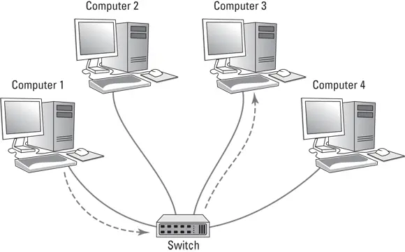
FIGURE 3-2:Unlike a hub, a switch knows where to send its data.
In order to accomplish intelligent forwarding, a switch must know what devices are connected to each of its ports. In the next section, you see how a switch learns what devices are connected to each of its ports.
Learning
For a switch to do its job, it needs to know what devices are connected to each of its ports. More specifically, the switch needs to know what MAC addresses are reachable via each of its ports. It does this in an ingeniously simple way: It simply learns. Whenever a packet is received on any of the switch’s ports, the switch examines the sending MAC address in the packet. The switch rightly assumes that if it received a packet from a given MAC address on a given port, the switch can reach that MAC address via that port. For example, if a switch receives a packet from Computer C on port 3, the switch has learned that Computer C is reachable on port 3. The switch adds this information to the MAC address table. This table is sometimes referred to as a forwarding database, because it keeps track of which port packets intended for a given destination should be forwarded to. The MAC address table simply keeps a tally of which MAC addresses are reachable on each port of the switch. Suppose the MAC address for Computer C is 21-76-3D-7A-F6-1E. If the switch receives a packet from port 3 with that MAC address, it would add the following entry to the MAC address table:
| Port | MAC Address |
|---|---|
| 3 | 21-76-3D-7A-F6-1E |
In this way, the switch has learned that Computer C is reachable via port 3.
After a short time, the switch will likely receive packets from all its ports and will associate the sender’s MAC address with each port:
| Port | MAC Address |
|---|---|
| 1 | 40-20-08-78-84-52 |
| 2 | 2F-B6-E0-F6-EA-05 |
| 3 | 21-76-3D-7A-F6-1E |
| 4 | 63-44-E4-A7-4F-E0 |
| 5 | 76-2F-F9-C8-B6-08 |
| 6 | FC-78-B6-07-52-EA |
| 7 | CD-34-E4-B3-2C-76 |
| 8 | 1C-FD-E0-63-21-C0 |
It’s important to keep in mind that a switch port might actually connect to more than one device. For example, suppose port 5 isn’t connected to a computer but to another switch, which in turn has three other computers connected to it. In that case, the first switch can receive packets from three different computers on port 5. Then, the switch records each distinct MAC address in its MAC address table, something like this:
| Port | MAC Address |
|---|---|
| 1 | 40-20-08-78-84-52 |
| 2 | 2F-B6-E0-F6-EA-05 |
| 3 | 21-76-3D-7A-F6-1E |
| 4 | 63-44-E4-A7-4F-E0 |
| 5 | 76-2F-F9-C8-B6-08 |
| 5 | D6-4E-69-86-E9-F7 |
| 5 | 06-C1-15-A2-BA-60 |
| 6 | FC-78-B6-07-52-EA |
| 7 | CD-34-E4-B3-2C-76 |
| 8 | 1C-FD-E0-63-21-C0 |
The process of building the MAC address table is called learning, and is one of the three basic functions of a switch. The other two are forwarding and flooding, as described in the next two sections.
Forwarding
Now that you know about the MAC address table, you should have a good idea of how a switch knows which ports to forward incoming packets to: The switch simply looks up the destination MAC address in the table and sends the packet out through the corresponding port.
For example, if the switch receives a packet on port 1 intended for MAC address CD-34-E4-B3-2C-76, the switch looks up that MAC address in the table, finds that the MAC address can be reached on port 7, and forwards the packet out to port 7. This process, called forwarding, is the second basic function of a switch.
Switches have memory buffers associated with each port that allow the switch to store a complete packet before forwarding it to the destination port. This allows the switch to hold onto the packet for a bit if necessary before forwarding it. For example, the destination port may be busy sending out a packet received from a different port. Or, the destination port may be busy receiving a packet. In either case, when the port becomes free, the switch can transmit the packet to its destination.
It’s important to understand that the switch does not modify the packet in any way prior to sending it. What gets sent out to the destination port is an exact replica of what was received on the incoming port. When the destination device receives the packet, the device has no idea that the packet passed through the switch. In other words, no tracing information is added to the packet by the switch.
It’s also important to know that, at least at this level of operation of the switch, the switch has no idea or concern for the contents of the Ethernet frame’s payload. In particular, the switch is not concerned with the possibility that the payload may be an IP packet, which in turn contains an IP address. Switching does not rely on or even know about IP addresses. Switching is a layer-2 function, and layer 2 is concerned with MAC addresses. IP addresses are a layer-3 concern and, thus, are hidden from switches.
Читать дальшеИнтервал:
Закладка:
Похожие книги на «Networking All-in-One For Dummies»
Представляем Вашему вниманию похожие книги на «Networking All-in-One For Dummies» списком для выбора. Мы отобрали схожую по названию и смыслу литературу в надежде предоставить читателям больше вариантов отыскать новые, интересные, ещё непрочитанные произведения.


Обсуждение, отзывы о книге «Networking All-in-One For Dummies» и просто собственные мнения читателей. Оставьте ваши комментарии, напишите, что Вы думаете о произведении, его смысле или главных героях. Укажите что конкретно понравилось, а что нет, и почему Вы так считаете.