Doug Lowe - Networking All-in-One For Dummies
Здесь есть возможность читать онлайн «Doug Lowe - Networking All-in-One For Dummies» — ознакомительный отрывок электронной книги совершенно бесплатно, а после прочтения отрывка купить полную версию. В некоторых случаях можно слушать аудио, скачать через торрент в формате fb2 и присутствует краткое содержание. Жанр: unrecognised, на английском языке. Описание произведения, (предисловие) а так же отзывы посетителей доступны на портале библиотеки ЛибКат.
- Название:Networking All-in-One For Dummies
- Автор:
- Жанр:
- Год:неизвестен
- ISBN:нет данных
- Рейтинг книги:4 / 5. Голосов: 1
-
Избранное:Добавить в избранное
- Отзывы:
-
Ваша оценка:
Networking All-in-One For Dummies: краткое содержание, описание и аннотация
Предлагаем к чтению аннотацию, описание, краткое содержание или предисловие (зависит от того, что написал сам автор книги «Networking All-in-One For Dummies»). Если вы не нашли необходимую информацию о книге — напишите в комментариях, мы постараемся отыскать её.
s covers all the basic and not-so-basic information you need to get a network up and running. It also helps you keep it running as it grows more complicated, develops bugs, and encounters all the fun sorts of trouble you expect from a complex system. Ideal both as a starter for newbie administrators and as a handy quick reference for pros, this book is built for speed, allowing you to get past all the basics—like installing and configuring hardware and software, planning your network design, and managing cloud services—so you can get on with what your network is actually intended to do.
In a friendly, jargon-free style, Doug Lowe—an experienced IT Director and prolific tech author—covers the essential, up-to-date information for networking in systems such as Linux and Windows 10 and clues you in on best practices for security, mobile, and more. Each of the nine minibooks demystifies the basics of one key area of network management.
Plan and administrate your network Implement virtualization Get your head around networking in the Cloud Lock down your security protocols The best thing about this book? You don’t have to read it all at once to get things done; once you’ve solved the specific issue at hand, you can put it down again and get on with your life. And the next time you need it, it’ll have you covered.
Networking All-in-One For Dummies — читать онлайн ознакомительный отрывок
Ниже представлен текст книги, разбитый по страницам. Система сохранения места последней прочитанной страницы, позволяет с удобством читать онлайн бесплатно книгу «Networking All-in-One For Dummies», без необходимости каждый раз заново искать на чём Вы остановились. Поставьте закладку, и сможете в любой момент перейти на страницу, на которой закончили чтение.
Интервал:
Закладка:
You learn more about how this works and why it’s so important in Chapter 3of this minibook.
Dealing with Broadcast Packets
Not all packets on an Ethernet network are intended for a single destination. Instead, some packets, called broadcast packets, are intended to be received by every device on the network. To send a broadcast packet, the sending interface sets the destination MAC address to FF-FF-FF-FF-FF-FF — that is, all ones. Then, all interfaces that receive the packet inspect the destination, see that the packet is a broadcast, and pass the packet up to the next higher protocol.
One of the most common users of broadcast packets is Dynamic Host Configuration Protocol (DHCP), which allows computers that join a network to be assigned an IP address. When a network interface is first connected to a network, it sends out a broadcast message requesting the address of the network’s DHCP server. Every device on the network sees this packet. But only the DHCP service will respond.
As you see in the next chapter, broadcast packets can sometimes cause a serious problem on your network. All networks should be planned in a way that minimizes problems caused by broadcast packets.
Examining Wireless Networks
As I mention in Chapter 1of this minibook, a wireless network is a network in which radio signals are used to connect devices to the network rather than physical cables. You learn much more about wireless networks in Book 2, Chapter 1, as well as Book 4, Chapter 2. But for now, I want you to keep the following points in mind:
Just like a wired network, a device connecting to a wireless network does so via a network interface. A wireless interface, also known as a wireless adapter, includes a radio transmitter and receiver rather than a physical cable connection.
Every wireless network adapter has a MAC address.
Rather than a switch or a hub, wireless devices connect to a wireless access point (WAP).
Collisions are possible (likely, actually) on a WAP, just as they are on a hub. Unfortunately, there is no equivalent to a wireless switch that reduces the collision problem. WAPs are essentially hubs in that every device that connects to the access point is competing for the same bandwidth. Whenever the WAP sends a packet, all devices connected to the access point must inspect the packet to determine the MAC address destination. And if two devices try to send packets at the same time, a collision will occur. This is one of the inherent reasons that wireless networking is slower than wired networking.
Chapter 3
Switches, Routers, and VLANs
IN THIS CHAPTER
 Considering the value of switches
Understanding how switches do their magic
Examining the role of routers
Getting to know VLANs
In this chapter, I dig deeper into two of the most basic and ubiquitous networking devices: switches and routers. Every network has at least one switch and one router, and all but the smallest networks have more than one switch. These components are the basic building blocks of networks, so understanding what they do and how they work is essential to properly designing, implementing, and maintaining a network that functions well.
Besides switches and routers, this chapter also introduces the concept of virtual local area networks (VLANs). A VLAN is a fancy technique that lets you split a single physical network into two or more logical networks. VLANs are one of the key techniques for organizing a network in a way that will allow the network to scale up as your organization grows. Small networks don’t need to worry about VLANs, but even in a relatively small network, it pays to know what VLANs are. Introducing VLANs into your network before you actually need them will simplify your life as your network grows.
Understanding Switches
In the previous chapter, I explain that a hub is a layer-1 device that simply repeats all incoming network data to all its output ports. In other words, if a hub has eight ports, any input data that arrives on port 1 will be amplified and repeated on ports 2 through 8. A hub is an unintelligent device — the hub doesn’t know or care what the intended destination of the incoming data is. It simply sends the data to all its ports, hoping that the intended recipient is on one of those ports. (Actually, using the term hope here is misleading, because as I said, the hub not only doesn’t know who the intended recipient is but doesn’t even care. Hubs have no capacity for hope.)
Figure 3-1 shows a simple network with four computers connected via a hub. In this example, Computer 1 is sending data to Computer 4. As the figure shows, the hub doesn’t know that the intended recipient is Computer 3, so it sends the data not just to Computer 3, but also to Computer 2 and Computer 3 as well.
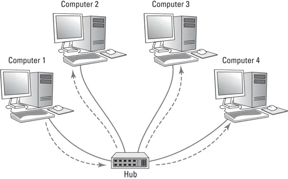
FIGURE 3-1:A hub repeats all incoming data on all its ports.
To understand why hubs even exist, or at least did exist in the distant past, we need a little history lesson. Ethernet was invented in the late 1970s and first became commercially available in 1980. From the very beginning, Ethernet used what is called shared media to connect devices in a network. The basic idea of Ethernet is that data is sent over network cables in the form of packets, which follow a well-defined structure. The key elements of the original Ethernet were (and still are) as follows:
All devices on the network can access all data sent over the network. That’s why the network cable itself is considered to be shared media.
Every device on the network has a unique identifier called a MAC address. I cover MAC addresses in the preceding chapter. As a quick reminder, MAC addresses are 48 bits long and are written as six octets separated by hyphens. For example, 21-76-3D-7A-F6-1E is a valid MAC address.
A data packet includes the MAC address of the packet’s intended recipient, as well as the MAC address of the sender.
Every device on the network receives every packet that is sent on the network and examines the destination MAC address to determine whether the packet is intended for it. If so, the device says, “Mine!” and stores the packet to be processed by other protocols higher up the food chain (that is, at higher levels in the OSI Reference Model). If the destination MAC address doesn’t match the device’s, the device says “Hmph!” and simply ignores the packet. All the devices on the network do this examination, keeping only the packets that belong to them and ignoring all the others.
If the destination MAC address is all ones (represented as FF-FF-FF-FF-FF-FF), the packet is called a broadcast packet. When a broadcast packet is sent, every device on the network looks at the destination MAC address, sees that the packet is a broadcast packet, and says, “Mine!” Broadcast packets are received by every device on the network.
Every once in a while, two devices try to send a packet at the exact same time. When that happens, both packets are garbled. The result is called a collision. When collisions happen, both senders wait for a brief amount of randomly generated time and then try again. The collision probably won’t happen again. But if it does, the senders wait and try again later.
Читать дальшеИнтервал:
Закладка:
Похожие книги на «Networking All-in-One For Dummies»
Представляем Вашему вниманию похожие книги на «Networking All-in-One For Dummies» списком для выбора. Мы отобрали схожую по названию и смыслу литературу в надежде предоставить читателям больше вариантов отыскать новые, интересные, ещё непрочитанные произведения.


Обсуждение, отзывы о книге «Networking All-in-One For Dummies» и просто собственные мнения читателей. Оставьте ваши комментарии, напишите, что Вы думаете о произведении, его смысле или главных героях. Укажите что конкретно понравилось, а что нет, и почему Вы так считаете.