Doug Lowe - Networking All-in-One For Dummies
Здесь есть возможность читать онлайн «Doug Lowe - Networking All-in-One For Dummies» — ознакомительный отрывок электронной книги совершенно бесплатно, а после прочтения отрывка купить полную версию. В некоторых случаях можно слушать аудио, скачать через торрент в формате fb2 и присутствует краткое содержание. Жанр: unrecognised, на английском языке. Описание произведения, (предисловие) а так же отзывы посетителей доступны на портале библиотеки ЛибКат.
- Название:Networking All-in-One For Dummies
- Автор:
- Жанр:
- Год:неизвестен
- ISBN:нет данных
- Рейтинг книги:4 / 5. Голосов: 1
-
Избранное:Добавить в избранное
- Отзывы:
-
Ваша оценка:
Networking All-in-One For Dummies: краткое содержание, описание и аннотация
Предлагаем к чтению аннотацию, описание, краткое содержание или предисловие (зависит от того, что написал сам автор книги «Networking All-in-One For Dummies»). Если вы не нашли необходимую информацию о книге — напишите в комментариях, мы постараемся отыскать её.
s covers all the basic and not-so-basic information you need to get a network up and running. It also helps you keep it running as it grows more complicated, develops bugs, and encounters all the fun sorts of trouble you expect from a complex system. Ideal both as a starter for newbie administrators and as a handy quick reference for pros, this book is built for speed, allowing you to get past all the basics—like installing and configuring hardware and software, planning your network design, and managing cloud services—so you can get on with what your network is actually intended to do.
In a friendly, jargon-free style, Doug Lowe—an experienced IT Director and prolific tech author—covers the essential, up-to-date information for networking in systems such as Linux and Windows 10 and clues you in on best practices for security, mobile, and more. Each of the nine minibooks demystifies the basics of one key area of network management.
Plan and administrate your network Implement virtualization Get your head around networking in the Cloud Lock down your security protocols The best thing about this book? You don’t have to read it all at once to get things done; once you’ve solved the specific issue at hand, you can put it down again and get on with your life. And the next time you need it, it’ll have you covered.
Networking All-in-One For Dummies — читать онлайн ознакомительный отрывок
Ниже представлен текст книги, разбитый по страницам. Система сохранения места последней прочитанной страницы, позволяет с удобством читать онлайн бесплатно книгу «Networking All-in-One For Dummies», без необходимости каждый раз заново искать на чём Вы остановились. Поставьте закладку, и сможете в любой момент перейти на страницу, на которой закончили чтение.
Интервал:
Закладка:
Cables: These run through walls and ceiling spaces, through conduits, between floors, and wherever else they need to go to reach their destinations.
Patch panels: These allow cables to be organized at a central location.
Network switches: A switch is an intermediate device that sits between the networked devices that allows those devices to communicate with each other. In a real way, switches are the core of the network; without switches, computers wouldn’t be able to talk.
Wireless access points: A wireless access point (or WAP and sometimes just AP ) lets devices connect wirelessly to the network. Depending on the size of your network and the physical space your users occupy, you may need more than one WAP. Each WAP needs to be connected to the LAN via a cabled switch connection.
At least one router: A router enables the network to the outside world. The most common use of a router is to connect the LAN to the Internet. However, routers can also be used to connect one LAN to another. I tell you more about routers in Chapter 3of this minibook.
Understanding Network Protocols and Standards
To operate efficiently, the infrastructure of a network consists of devices that conform to well-known standards and protocols. A protocol provides a precise sequence of steps that each element of a network must follow to enable communications. Protocols also define the precise format of all data that is exchanged in a network. For example, the Internet Protocol (IP) defines the format of IP addresses: four eight-bit numbers called octets whose decimal values range from 0 to 255, as in 10.0.101.155.
A standard is a detailed definition of a protocol that has been established by a standards organization and that vendors follow when they create products. Without standards, it would be impossible for one vendor’s products to work with another vendor’s. Because of standards, you can instead purchase equipment from different vendors with the assurance that they’ll work together.
Network standards are organized into a framework called the Open Systems Interconnection (OSI) Reference Model. The OSI Reference Model establishes a hierarchy for protocols so that each protocol can deal with just one part of the overall task of data communications. The OSI Reference Model identifies seven distinct layers at which a protocol may operate:
Physical (layer 1): Describes the mechanical and electrical details of network components such as cables, connectors, and network interfaces.
Data link (layer 2): Describes the basic techniques that networks use to uniquely identify devices on the network (typically via a MAC address) and the means for one device to send information over the physical layer to another device, in the form of data packets. Switches operate at the data link layer, which means that they manage the efficient transmission of data packets from one device to another.
Network (layer 3): Handles the routing of data across networks. Routers operate at the network layer.
Transport (layer 4): Provides for reliable delivery of packets.
Session (layer 5): Establishes sessions between network applications.
Presentation (layer 6): Converts data so that systems that use different data formats can exchange information.
Application (layer 7): Allows applications to request network services.
Although the upper layers of the OSI model (layers 4 through 7) are equally important, in this chapter and the next, I focus on the first three layers of the OSI model — physical, data link, and network. These layers are the ones where the most common types of networking hardware such as cables, interfaces, switches, and routers operate.
Although many different network protocols and standards can be used in various layers of the OSI model, the most common standard found at layers 1 and 2 is Ethernet. Similarly, the most common standard at layer 3 is IP. I cover more about Ethernet and IP in Chapters 2and 3of Book 2, but keep in mind that most of what follows in this chapter is related to Ethernet and IP.
Recognizing Network Topology
The term network topology refers to the shape of how the computers and other network components are connected to each other. Several different types of network topologies exist, each with advantages and disadvantages.
 In the following discussion of network topologies, I use two important terms:
Node: A node is a device that’s connected to the network. For your purposes here, a node is the same as a computer. Network topology deals with how the nodes of a network are connected to each other.
Packet: A packet is a message that’s sent over the network from one node to another node. The packet includes the address of the node that sent the packet, the address of the node the packet is being sent to, and data.
Bus topology
The first type of network topology is called a bus, in which nodes are strung together in a line, as shown in Figure 2-1. The key to understanding how a bus topology works is to think of the entire network as a single cable, with each node “tapping” into the cable so it can listen in on the packets being sent over that cable. If you’re old enough to remember party lines, you get the idea.
In a bus topology, every node on the network can see every packet that’s sent on the cable. Each node looks at each packet to determine whether the packet is intended for it. If so, the node claims the packet. If not, the node ignores the packet. This way, each computer can respond to data sent to it and ignore data sent to other computers on the network.
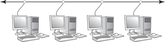
FIGURE 2-1:Bus topology.
If the cable in a bus network breaks, the entire network is effectively disabled. Obviously, the nodes on opposite sides of the break can continue to communicate with each other, because data can’t span the gap created by the break. But even those nodes that are on the same side of the break may not be able to communicate with each other, because the open end of the cable left by the break disrupts the proper transmission of electrical signals.
In the early days of Ethernet networking, bus topology was commonplace. Although, for most networks, bus topology has given way to star topology (see the next section), many networks today still have elements that rely on bus topology.
Star topology
In a star topology, each network node is connected to a central device called a hub or a switch, as shown in Figure 2-2. Star topologies are commonly used with LANs.
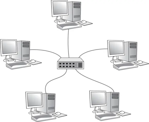
FIGURE 2-2:Star topology.
If a cable in a star network breaks, only the node connected to that cable is isolated from the network. The other nodes can continue to operate without interruption — unless, of course, the node that’s isolated because of the break happens to be the file server.
 You should be aware of the somewhat technical distinction between a hub and a switch. Simply put, a hub doesn’t know anything about the computers that are connected to each of its ports. So, when a computer connected to the hub sends a packet to a computer that’s connected to another port, the hub sends a duplicate copy of the packet to all its ports. In contrast, a switch knows which computer is connected to each of its ports. As a result, when a switch receives a packet intended for a particular computer, it sends the packet only to the port that the recipient is connected to.
Интервал:
Закладка:
Похожие книги на «Networking All-in-One For Dummies»
Представляем Вашему вниманию похожие книги на «Networking All-in-One For Dummies» списком для выбора. Мы отобрали схожую по названию и смыслу литературу в надежде предоставить читателям больше вариантов отыскать новые, интересные, ещё непрочитанные произведения.


Обсуждение, отзывы о книге «Networking All-in-One For Dummies» и просто собственные мнения читателей. Оставьте ваши комментарии, напишите, что Вы думаете о произведении, его смысле или главных героях. Укажите что конкретно понравилось, а что нет, и почему Вы так считаете.