Michael Graham - Wind Energy Handbook
Здесь есть возможность читать онлайн «Michael Graham - Wind Energy Handbook» — ознакомительный отрывок электронной книги совершенно бесплатно, а после прочтения отрывка купить полную версию. В некоторых случаях можно слушать аудио, скачать через торрент в формате fb2 и присутствует краткое содержание. Жанр: unrecognised, на английском языке. Описание произведения, (предисловие) а так же отзывы посетителей доступны на портале библиотеки ЛибКат.

- Название:Wind Energy Handbook
- Автор:
- Жанр:
- Год:неизвестен
- ISBN:нет данных
- Рейтинг книги:3 / 5. Голосов: 1
-
Избранное:Добавить в избранное
- Отзывы:
-
Ваша оценка:
Wind Energy Handbook: краткое содержание, описание и аннотация
Предлагаем к чтению аннотацию, описание, краткое содержание или предисловие (зависит от того, что написал сам автор книги «Wind Energy Handbook»). Если вы не нашли необходимую информацию о книге — напишите в комментариях, мы постараемся отыскать её.
delivers a fully updated treatment of key developments in wind technology since the publication of the book’s Second Edition in 2011. The criticality of wakes within wind farms is addressed by the addition of an entirely new chapter on wake effects, including ‘engineering’ wake models and wake control. Offshore, attention is focused for the first time on the design of floating support structures, and the new ‘PISA’ method for monopile geotechnical design is introduced.
The coverage of blade design has been completely rewritten, with an expanded description of laminate fatigue properties and new sections on manufacturing methods, blade testing, leading-edge erosion and bend-twist coupling. These are complemented by new sections on blade add-ons and noise in the aerodynamics chapters, which now also include a description of the Leishman-Beddoes dynamic stall model and an extended introduction to Computational Fluid Dynamics analysis.
The importance of the environmental impact of wind farms both on- and offshore is recognised by extended coverage, which encompasses the requirements of the Grid Codes to ensure wind energy plays its full role in the power system. The conceptual design chapter has been extended to include a number of novel concepts, including low induction rotors, multiple rotor structures, superconducting generators and magnetic gearboxes.
References and further reading resources are included throughout the book and have been updated to cover the latest literature. Importantly, the core subjects constituting the essential background to wind turbine and wind farm design are covered, as in previous editions. These include:
The nature of the wind resource, including geographical variation, synoptic and diurnal variations and turbulence characteristics The aerodynamics of horizontal axis wind turbines, including the actuator disc concept, rotor disc theory, the vortex cylinder model of the actuator disc and the Blade-Element/Momentum theory Design loads for horizontal axis wind turbines, including the prescriptions of international standards Alternative machine architectures The design of key components Wind turbine controller design for fixed and variable speed machines The integration of wind farms into the electrical power system Wind farm design, siting constraints and the assessment of environmental impact Perfect for engineers and scientists learning about wind turbine technology, the
will also earn a place in the libraries of graduate students taking courses on wind turbines and wind energy, as well as industry professionals whose work requires a deep understanding of wind energy technology.
Wind Energy Handbook — читать онлайн ознакомительный отрывок
Ниже представлен текст книги, разбитый по страницам. Система сохранения места последней прочитанной страницы, позволяет с удобством читать онлайн бесплатно книгу «Wind Energy Handbook», без необходимости каждый раз заново искать на чём Вы остановились. Поставьте закладку, и сможете в любой момент перейти на страницу, на которой закончили чтение.
Интервал:
Закладка:
Dimensional analysis shows that in low‐speed, steady flow (that is, flow at low Mach number, so that the relative speed of the flow is much less than the speed of sound), the lift L and drag D may be expressed in the form of non‐dimensional parameters, the lift and drag coefficients:
which are both functions of the Reynolds number,

of the flow.
Here ρ is the density and ν the kinematic viscosity of the fluid, in this case air, U is the flow speed, l is a characteristic length scale (often the mean chord c), and A is an appropriate area of the body. In the case of aerofoils, wings, or turbine blades, A is usually taken to be the plan‐form area s.c, where s is the span of the whole body or of a section of the body on which the force is evaluated. Most ‘lifting surfaces’ that are designed to provide lift with minimum accompanying drag, such as the wings of subsonic aircraft and the blades of high tip speed ratio HAWTs, are of high aspect ratio with relatively gradual changes of section (chord c, thickness, camber, and twist) with respect to the spanwise direction. For these bodies the aspect ratio is defined as the span of the blade or wings divided by the mean chord. For aircraft the span is defined as the distance between the two wing tips of the wing pair, but in the case of a wind turbine, the span is the distance from the axis of rotation to the tip of a single blade. Because of the gradual variation of properties along a wing or blade, it is very convenient and in practice sufficiently accurate usually to analyse whole wing or blade forces in terms of the sum of sectional forces and sectional force coefficients. This is taken up in Section A3.8.
This form of non‐dimensionalisation is used because it is found that for similar configurations over most regimes involving air (or water), flows of typical speeds and length scales of most practical flows, force coefficients expressed in this way vary relatively slowly with respect to the other main non‐dimensional parameter of the flow, the Reynolds number. Expressing flow‐induced forces in term of these coefficients is particularly convenient when testing flows at model scale or comparing forces induced on similar shaped bodies in different fluids or flow speeds. Typical Reynolds numbers relevant to flow around wind turbine blades are of order 10 6to 10 7(order 10 5for small rotors of diameter ∼1 m). In this context the term ‘low Reynolds number’ is often used to describe flows where the Reynolds number is less than about 10 5. This regime can occur in wind‐tunnel testing of small model turbines. Strictly in fluid dynamics, the term ‘low Reynolds number’ refers to the Stokes flow regime for which the Reynolds number is of order 1 and the flow approximately satisfies the Stokes Equations. It is not relevant here. It should be noted that the factor ½ was not originally in the denominator in the definition of these coefficients but was introduced later in further development of the subjects of fluid dynamics during the twentieth century because of its occurrence in related terms in Bernoulli's equation for pressure. It is now established in use for all force, pressure, and power coefficient definitions but is not completely universal, being, for example, omitted in US definitions of rotor power and thrust coefficients for helicopters.
A3.1 Drag
Flow‐induced forces on a body in a viscous fluid arise from:
1 A tangential stress exerted on the surface, the skin friction, which is caused directly by the viscosity in the fluid coupled with the fact that there cannot be any relative motion of a viscous fluid with respect to the body at its surface, the no‐slip condition.
2 A normal stress exerted at the surface, the pressure.
Both types of stress contribute to the drag.
It is convenient to consider the drag exerted on 2‐D bodies across a uniform flow, because many general practical bodies are of a configuration that has one long cross‐flow dimension such that the flow varies only gradually in that ‘long’ direction. In such cases, 2‐D flow is a good local approximation to the flow about any section of the body normal to the long axis. These configurations may be termed quasi‐2‐D . Wind turbine blades and towers are examples of such bodies.
All fluids (with a very few special exceptions, such as liquid helium) have some viscosity, although in the case of two of the most common fluids, air and water, it is relatively small. In the absence of any viscous effect, the flow slips relative to the body at its surface, can be described by a potential function, and is called potential flow . The drag in this case on a 2‐D body in fully subsonic, steady inviscid flow is exactly zero because no wake is generated.
The action of viscosity is to diffuse vorticity and hence momentum in a way analogous to the diffusion of heat, out from the body surface where the flow is retarded by the no‐slip condition, which now applies at the surface. If the fluid has small kinematic viscosity and a comparatively large length scale and velocity so that the Reynolds number is high, the viscous diffusion effects spread outwards at a very much slower speed than the main velocity convection speed along the body surface and as a result remain confined to a thin layer adjacent to the body surface, the boundary layer.
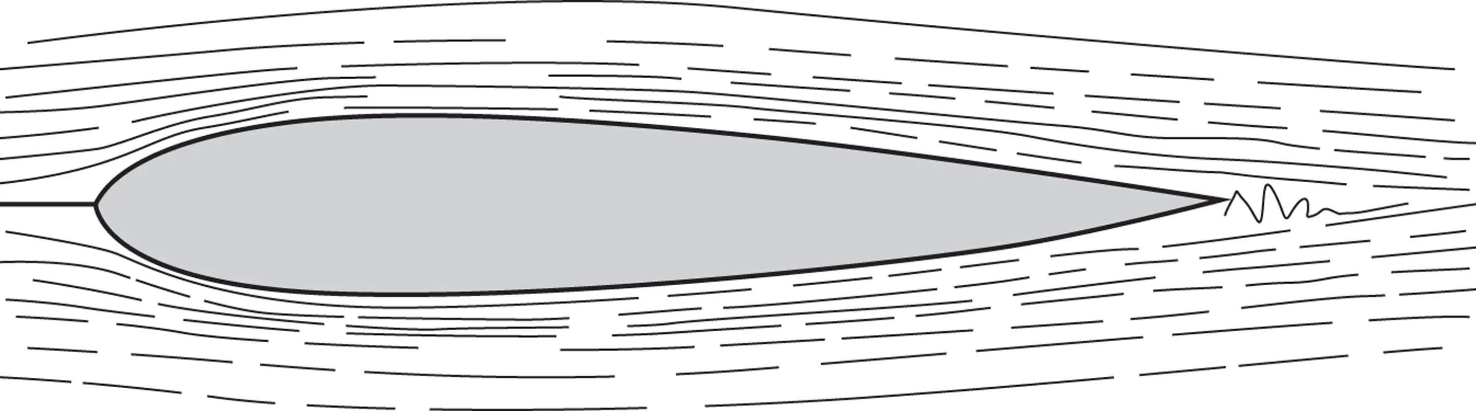
Figure A3.1 Flow past a streamlined body.
Generally, bodies are subdivided into two categories: streamlined and bluff. The main characteristics of streamlined bodies (see, e.g. Figure A3.1) are that the boundary layers remain thin over the whole body surface to the rearmost part of the body, where they recombine and stream off in a thin wake and the drag coefficient is comparatively small. Bodies such as wings and rotor blades whose sections are aerofoils are examples. Bodies on which not all of the boundary layers remain attached in this way up to a trailing edge but rather detach at earlier points creating a thick wake are termed bluff bodies . The flows around such bodies, for example, circular cylinders and fully stalled aerofoils (see Figure A3.12), result in a comparatively high drag coefficient. More general 3‐D bodies may also belong to another category, that of slender bodies (slender in the flow direction), which are not relevant here.
Many practical bodies such as wind turbines or aircraft involve a complex assembly of components that individually belong to the preceding categories. Forces on such bodies are usually calculated by breaking the body down into quasi‐2‐D elements, and interactions between elements are dealt with, when significant, by interference coefficients. In some cases where it is appropriate to consider sectional flow, such as for the blades of a wind turbine, the flow is not exactly in the plane of the section and may contain a non‐zero ‘lengthwise’ or transverse component. It is usual and can be demonstrated that if boundary layer effects are neglected, the pressures and forces on any body section normal to the long axis result from only those flow components that are in the plane of the section and are insensitive to the velocity component parallel to the long axis. This is known as the independence principle and holds quite accurately for real attached viscous flows up to angles of yaw between the flow and the long axis from normal flow (0° of yaw) to about 45° of yaw. This covers the usual range for such elements as wind turbine blades. For larger yaw angles than this the independence principle is increasingly in error, and as the yaw angle approaches 90° the flow becomes more like that of a slender body.
Читать дальшеИнтервал:
Закладка:
Похожие книги на «Wind Energy Handbook»
Представляем Вашему вниманию похожие книги на «Wind Energy Handbook» списком для выбора. Мы отобрали схожую по названию и смыслу литературу в надежде предоставить читателям больше вариантов отыскать новые, интересные, ещё непрочитанные произведения.


Обсуждение, отзывы о книге «Wind Energy Handbook» и просто собственные мнения читателей. Оставьте ваши комментарии, напишите, что Вы думаете о произведении, его смысле или главных героях. Укажите что конкретно понравилось, а что нет, и почему Вы так считаете.