Michael Graham - Wind Energy Handbook
Здесь есть возможность читать онлайн «Michael Graham - Wind Energy Handbook» — ознакомительный отрывок электронной книги совершенно бесплатно, а после прочтения отрывка купить полную версию. В некоторых случаях можно слушать аудио, скачать через торрент в формате fb2 и присутствует краткое содержание. Жанр: unrecognised, на английском языке. Описание произведения, (предисловие) а так же отзывы посетителей доступны на портале библиотеки ЛибКат.

- Название:Wind Energy Handbook
- Автор:
- Жанр:
- Год:неизвестен
- ISBN:нет данных
- Рейтинг книги:3 / 5. Голосов: 1
-
Избранное:Добавить в избранное
- Отзывы:
-
Ваша оценка:
Wind Energy Handbook: краткое содержание, описание и аннотация
Предлагаем к чтению аннотацию, описание, краткое содержание или предисловие (зависит от того, что написал сам автор книги «Wind Energy Handbook»). Если вы не нашли необходимую информацию о книге — напишите в комментариях, мы постараемся отыскать её.
delivers a fully updated treatment of key developments in wind technology since the publication of the book’s Second Edition in 2011. The criticality of wakes within wind farms is addressed by the addition of an entirely new chapter on wake effects, including ‘engineering’ wake models and wake control. Offshore, attention is focused for the first time on the design of floating support structures, and the new ‘PISA’ method for monopile geotechnical design is introduced.
The coverage of blade design has been completely rewritten, with an expanded description of laminate fatigue properties and new sections on manufacturing methods, blade testing, leading-edge erosion and bend-twist coupling. These are complemented by new sections on blade add-ons and noise in the aerodynamics chapters, which now also include a description of the Leishman-Beddoes dynamic stall model and an extended introduction to Computational Fluid Dynamics analysis.
The importance of the environmental impact of wind farms both on- and offshore is recognised by extended coverage, which encompasses the requirements of the Grid Codes to ensure wind energy plays its full role in the power system. The conceptual design chapter has been extended to include a number of novel concepts, including low induction rotors, multiple rotor structures, superconducting generators and magnetic gearboxes.
References and further reading resources are included throughout the book and have been updated to cover the latest literature. Importantly, the core subjects constituting the essential background to wind turbine and wind farm design are covered, as in previous editions. These include:
The nature of the wind resource, including geographical variation, synoptic and diurnal variations and turbulence characteristics The aerodynamics of horizontal axis wind turbines, including the actuator disc concept, rotor disc theory, the vortex cylinder model of the actuator disc and the Blade-Element/Momentum theory Design loads for horizontal axis wind turbines, including the prescriptions of international standards Alternative machine architectures The design of key components Wind turbine controller design for fixed and variable speed machines The integration of wind farms into the electrical power system Wind farm design, siting constraints and the assessment of environmental impact Perfect for engineers and scientists learning about wind turbine technology, the
will also earn a place in the libraries of graduate students taking courses on wind turbines and wind energy, as well as industry professionals whose work requires a deep understanding of wind energy technology.
Wind Energy Handbook — читать онлайн ознакомительный отрывок
Ниже представлен текст книги, разбитый по страницам. Система сохранения места последней прочитанной страницы, позволяет с удобством читать онлайн бесплатно книгу «Wind Energy Handbook», без необходимости каждый раз заново искать на чём Вы остановились. Поставьте закладку, и сможете в любой момент перейти на страницу, на которой закончили чтение.
Интервал:
Закладка:
Vortex generators (VGs) are small triangular, rectangular, or similar pieces of flat, rigid sheet that act as very small half‐wings of low aspect ratio set perpendicular to the blade surface at a large angle of incidence (∼30°) to the local flow direction, as shown in Figure 3.75. Such plates generate strong leading edge (triangular delta VGs) or tip (rectangular VGs) vortices. The vortices stream over the main blade surface, stirring up the flow in the boundary layer, re‐energising the lower (inner) layers by bringing flow down from the upper (outer) layers and hence inhibiting separation. It is found that a line of small devices of this type of height about equal to the boundary layer thickness δ are very effective in inhibiting separation on the blade when placed a moderate distance upstream of the expected line of separation. VGs are easily added to the blade by fixing them via a lug at the base and are usually set to have an alternating positive and negative angle of incidence so that the rotation direction of the vortices alternates. They may be set moderately close together as in the example in the figure or farther apart up to the order of 10δ to still retain continuous effectiveness over the downstream region. In this way C Lmaxcan be increased. The main drawback of such devices is that being fixed passive devices they operate continuously even when not required, and because they continue to generate vortices, they increase slightly the pre‐stall drag of the blade.
Micro VGs are much smaller versions of ordinary VGs, being of order δ /10 in height and spaced somewhat more closely. Micro VGs operate in the inner region of the boundary layer, where for a turbulent boundary layer much the strongest part of the velocity gradient normal to the blade surface exists. They can be nearly as effective as standard VGs in suppressing separation and have the advantage of generating a smaller increase in drag.
Surface air jets are inclined jets sited in a similar location as VGs would be sited but rather closer together. The jets are often fed by higher‐pressure air from near the stagnation region of the blade section or sometimes from inboard regions taking advantage of the centrifugal pressure difference between inboard locations and those farther outboard. The jets act to re‐energise the lower boundary layer through their own momentum and thus prevent stalling. They have the advantage that they can be turned off when not required. Their main disadvantage is the additional complexity, ‘plumbing’, and therefore cost required to provide each jet and the vulnerability of the jet slots.
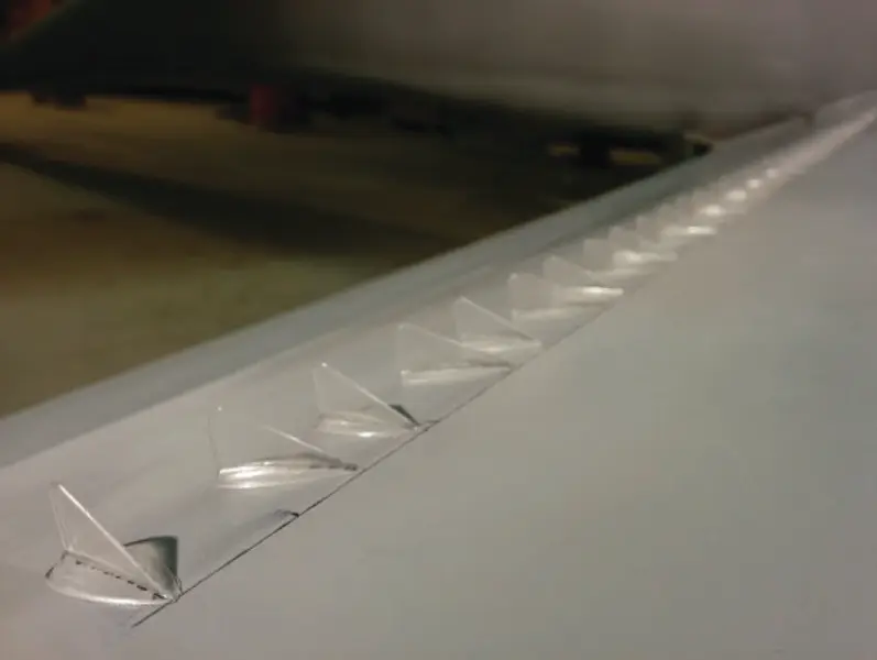
Figure 3.75 VGs on a blade suction surface. (Flow is from right to left.)
Massless or synthetic jets are a variation of surface air jets that operate by an oscillating piston within a cavity that forces a pulsatile jet out through a small hole in the blade surface. No net mean mass flow occurs, hence their name, equal mass flows occurring into and out of the orifice. During the intake phase the flow is a sink flow that produces relatively little disturbance, whereas the outflow phase is a jet that forms a vortex ring so that the oscillatory operation of the device generates a sequence of vortex rings that can re‐energise the boundary layer. No separate intake or piping is required, but each device (orifice) must be separately actuated. They are not as yet used on wind turbine blades but may be an option for the future because they have been found effective in controlling separation in other situations. They appear to be reasonably unaffected by dirt due to the exhaust phase in each cycle.
3.18.2 Devices to increase C Lmaxand lift/drag ratio
Deployable conventional flaps (see Figure 3.76a) are trailing edge flaps (TE flaps), leading edge flaps being very unusual, and are similar to conventional aircraft control surfaces such as ailerons, hinged at the rear of the blade section and operated by a mechanical actuator. They increase or decrease section lift by increasing or decreasing the effective camber of the blade section. They have been proposed for wind turbine blades but are rarely ever used because of the additional mechanical complexity, weight near the blade tips where they would be most useful, cost, and maintenance issues. Their main advantage is that they can be sited where changes in lift are most useful, typically outboard regions. As turbine blade lengths increase and the blades become ever more flexible, this localisation offers the possibility of distributed control with advantages over pitch control at the blade root, and it is possible that more use will be made of them in future. This is particularly relevant for active control to mitigate the effect of turbulence and gusts because small flaps can be actuated very rapidly and act locally.
Morphing blade sections ( Figure 3.76b) are a recent development that is really a variation of the conventional trailing edge flap. The actuator is within the rear section of the blade, which is fabricated from a flexible composite. The result when actuated is to generate a flap effect but with a more smoothly curved camber and with all mechanical parts protected by being internal and hence presumed to be less vulnerable to dirt and corrosion. The continuous curvature of the camber can be tailored for maximum aerodynamic efficiency. The technology is considered to be a promising method of providing distributed control with some mechanical benefits over conventional TE flaps.
Fixed (Gurney) flaps ( Figure 3.76c, named after Dan Gurney, who invented this flap for down‐force wings used in motor racing) are small fixed flaps in the form of a length of thin, right‐angle bar section fixed to the trailing edge of a blade on the pressure side. A Gurney flap is thus like a small trailing edge flap deployed at 90° in the direction to increase lift. Such flaps usually have a flap chord (i.e. ‘height’ from the blade) equal to only 1% or 2% of the blade section chord. With that small length but large deployment angle, a useful increase in lift coefficient (0.1 to 0.25) can be obtained at the expense of a small increase in drag coefficient. The result with a well‐designed flap is that the lift coefficient can be increased while the lift/drag ratio remains constant or may even increase slightly. See, for example, Giguere et al. (1997).
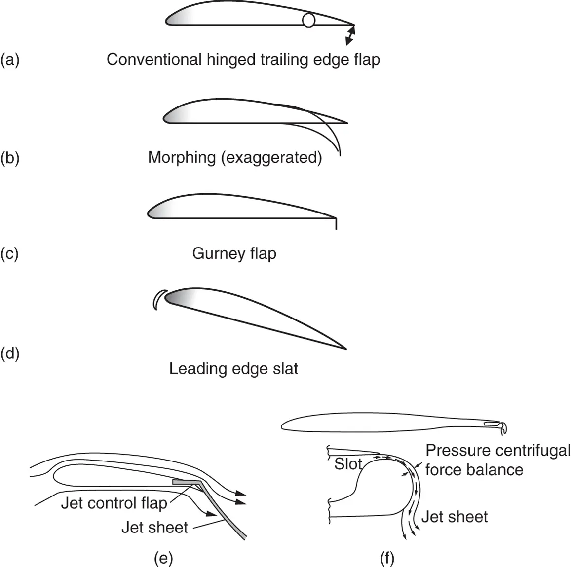
Figure 3.76 Flaps and similar acting devices: (a) conventional trailing edge flap, (b) morphing rear blade section, (c) Gurney flap, (d) leading edge slat, (e) jet flap, and (f) circulation control.
Slats ( Figure 3.76d), as deployed at the leading edges of aircraft wings to prevent separation during high angle of attack operation (during take‐off and landing), have also been tried on wind turbine blades for the same reason.
3.18.3 Circulation control (jet flaps)
The circulation and hence the lift around an aerofoil section can be controlled very rapidly by the action of a jet applied at the trailing edge. The jet may be directed over the suction surface of the blade at the trailing edge. This may simply have a suitably oriented exhaust nozzle ( Figure 3.76e) or may use the Coanda effect running over a short length of curved surface ( Figure 3.76f[lower]) to generate a jet sheet deflected so as to increase the effective camber of the section and hence the lift. It acts in a manner very similar to a conventional structural flap, hence is known as a jet flap , and is as shown in Figure 3.76e. Alternatively, jets may be emitted from slots either side of a rounded trailing edge to produce a highly deflected jet in either direction to control the circulation and hence the lift on the blade section, as shown in Figure 3.76f(upper). Figure 3.77shows a plot of lift coefficient vs jet momentum coefficient for a device of this type where the jet momentum coefficient Cμ = 2(U J /U ∞ ) 2 .t/c , U Jis the jet velocity and t it should be noted is the thickness of the jet exit slot (not to be confused here with the maximum thickness of the aerofoil section). Very high values of lift coefficient are possible if sufficient jet momentum is applied with a large deflection angle because the jet momentum removes the separation limit of a conventional flap.
Читать дальшеИнтервал:
Закладка:
Похожие книги на «Wind Energy Handbook»
Представляем Вашему вниманию похожие книги на «Wind Energy Handbook» списком для выбора. Мы отобрали схожую по названию и смыслу литературу в надежде предоставить читателям больше вариантов отыскать новые, интересные, ещё непрочитанные произведения.


Обсуждение, отзывы о книге «Wind Energy Handbook» и просто собственные мнения читателей. Оставьте ваши комментарии, напишите, что Вы думаете о произведении, его смысле или главных героях. Укажите что конкретно понравилось, а что нет, и почему Вы так считаете.