Michael Graham - Wind Energy Handbook
Здесь есть возможность читать онлайн «Michael Graham - Wind Energy Handbook» — ознакомительный отрывок электронной книги совершенно бесплатно, а после прочтения отрывка купить полную версию. В некоторых случаях можно слушать аудио, скачать через торрент в формате fb2 и присутствует краткое содержание. Жанр: unrecognised, на английском языке. Описание произведения, (предисловие) а так же отзывы посетителей доступны на портале библиотеки ЛибКат.

- Название:Wind Energy Handbook
- Автор:
- Жанр:
- Год:неизвестен
- ISBN:нет данных
- Рейтинг книги:3 / 5. Голосов: 1
-
Избранное:Добавить в избранное
- Отзывы:
-
Ваша оценка:
Wind Energy Handbook: краткое содержание, описание и аннотация
Предлагаем к чтению аннотацию, описание, краткое содержание или предисловие (зависит от того, что написал сам автор книги «Wind Energy Handbook»). Если вы не нашли необходимую информацию о книге — напишите в комментариях, мы постараемся отыскать её.
delivers a fully updated treatment of key developments in wind technology since the publication of the book’s Second Edition in 2011. The criticality of wakes within wind farms is addressed by the addition of an entirely new chapter on wake effects, including ‘engineering’ wake models and wake control. Offshore, attention is focused for the first time on the design of floating support structures, and the new ‘PISA’ method for monopile geotechnical design is introduced.
The coverage of blade design has been completely rewritten, with an expanded description of laminate fatigue properties and new sections on manufacturing methods, blade testing, leading-edge erosion and bend-twist coupling. These are complemented by new sections on blade add-ons and noise in the aerodynamics chapters, which now also include a description of the Leishman-Beddoes dynamic stall model and an extended introduction to Computational Fluid Dynamics analysis.
The importance of the environmental impact of wind farms both on- and offshore is recognised by extended coverage, which encompasses the requirements of the Grid Codes to ensure wind energy plays its full role in the power system. The conceptual design chapter has been extended to include a number of novel concepts, including low induction rotors, multiple rotor structures, superconducting generators and magnetic gearboxes.
References and further reading resources are included throughout the book and have been updated to cover the latest literature. Importantly, the core subjects constituting the essential background to wind turbine and wind farm design are covered, as in previous editions. These include:
The nature of the wind resource, including geographical variation, synoptic and diurnal variations and turbulence characteristics The aerodynamics of horizontal axis wind turbines, including the actuator disc concept, rotor disc theory, the vortex cylinder model of the actuator disc and the Blade-Element/Momentum theory Design loads for horizontal axis wind turbines, including the prescriptions of international standards Alternative machine architectures The design of key components Wind turbine controller design for fixed and variable speed machines The integration of wind farms into the electrical power system Wind farm design, siting constraints and the assessment of environmental impact Perfect for engineers and scientists learning about wind turbine technology, the
will also earn a place in the libraries of graduate students taking courses on wind turbines and wind energy, as well as industry professionals whose work requires a deep understanding of wind energy technology.
Wind Energy Handbook — читать онлайн ознакомительный отрывок
Ниже представлен текст книги, разбитый по страницам. Система сохранения места последней прочитанной страницы, позволяет с удобством читать онлайн бесплатно книгу «Wind Energy Handbook», без необходимости каждый раз заново искать на чём Вы остановились. Поставьте закладку, и сможете в любой момент перейти на страницу, на которой закончили чтение.
Интервал:
Закладка:
The operational speed range will be between the cut‐in speed and the cut‐out speed. The cut‐in speed is determined by the transmission losses: at what wind speed does the turbine begin to generate power? The cut‐in speed is usually chosen to be somewhat higher than the zero power speed, in the present case, say 4 m/s.
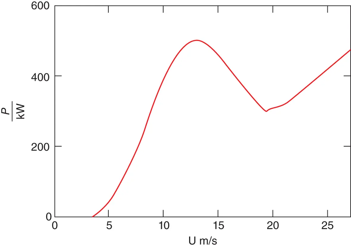
Figure 3.65 Power vs wind speed.
The cut‐out speed is chosen to protect the turbine from high loads, usually about 25 m/s.
The total energy captured ( E ) by the turbine in a time period T is
(3.101) 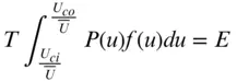
which is the area under the curve of Figure 3.66times the time T . Unfortunately, the integral does not have a closed mathematical form in general, and so a numerical integration is required, such as the trapezoidal rule or, for better accuracy, Simpson's rule.
For a time period of one year, the energy capture can be calculated numerically as indicated in Figure 3.67to be
(3.102) 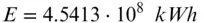
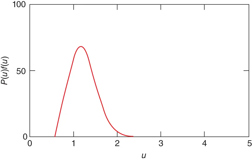
Figure 3.66 Energy capture curve.
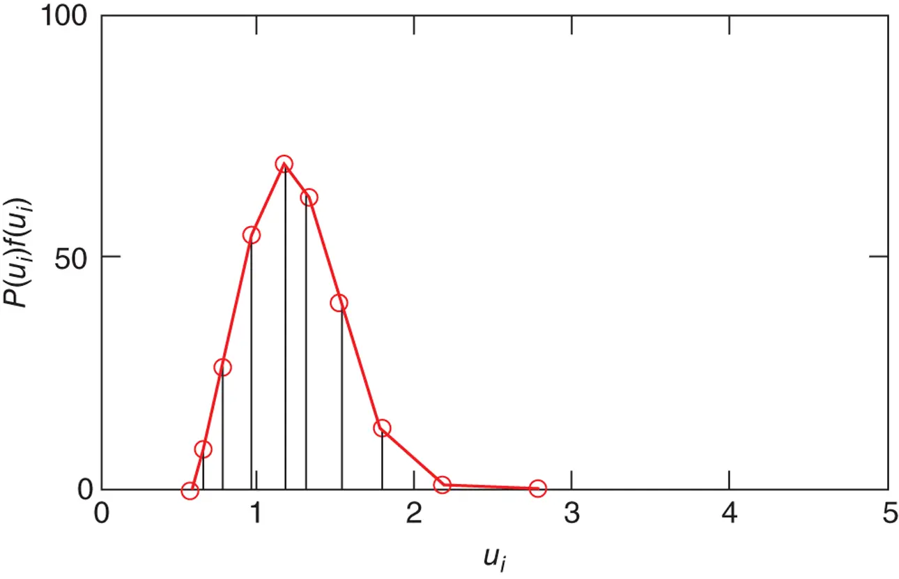
Figure 3.67 Energy capture curve for numerical integration.
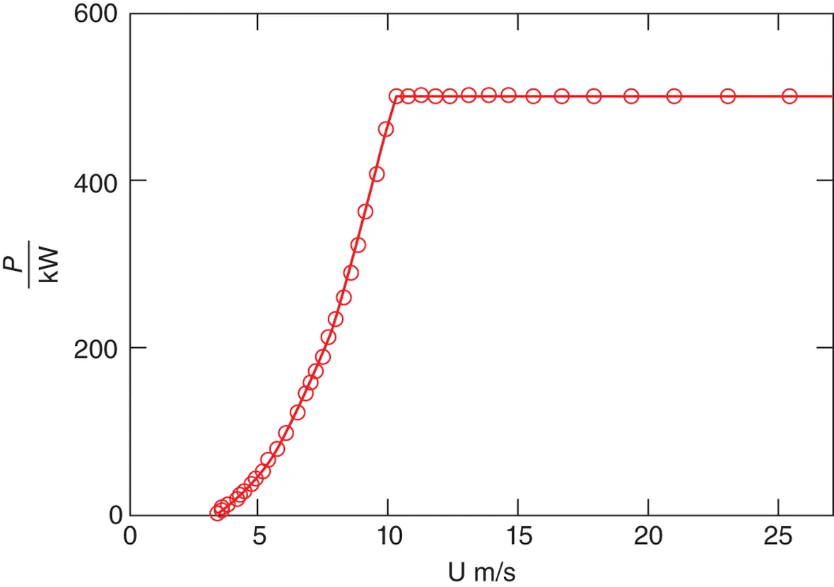
Figure 3.68 Power vs wind speed for variable‐speed turbine.
The upper limit of integration u co= 4.17 in this case is well above the highest value of u shown in Figure 3.67for which there is any significant energy.
A turbine that has pitch control would be able to capture more energy but at the expense of providing the control system and the concomitant reduction in reliability. A turbine operating at variable speed (constant tip speed ratio) until maximum power is reached and thence at constant speed and pitch control would capture the maximum possible amount of energy in a given time. The power curve for such a machine is shown in Figure 3.68.
The annual energy capture would be 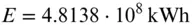 which is a 6% increase in energy capture compared with the fixed‐speed, stall‐regulated machine. Variable‐speed operation has a number of other advantages that are discussed in Section 6.9.4; it is increasingly being implemented.
3.17 Wind turbine aerofoil design
3.17.1 Introduction
For many years the wind turbine industry relied on aeronautical experience for the aerodynamic design of turbine blades, but it became clear that aerofoil sections that were optimum for aircraft wings were not necessarily optimum for wind turbine blades.
A major problem for modern wind turbines in the early years of development was sensitivity to insect deposition on the leading edge regions of the blades. There were reports of turbines in the 1970s having to be regularly hosed with water to clear accumulated debris on the blades to restore power levels that had fallen dramatically. An aerofoil that was tolerant to leading edge roughness was required.
Most early turbines of rated power greater than about 50 kW operated at constant rotational speed and relied upon passive stall for power control. With many aircraft aerofoil sections, the stall produced a sudden sharp loss of power output that was not recovered until the wind speed increased. The stalling resulted in significant losses of energy capture. Thus another requirement for a wind turbine aerofoil was a gentle stall.
Aerofoil stall occurs when the boundary layer on the low‐pressure surface starts to separate at some point before the trailing edge is reached, as shown in Figure A3.12. This process, which is due to sufficiently long and strong regions of rising surface pressure following the ‘suction peak’, is discussed in more detail in A3.3. The process is strongly dependent on the state of the boundary layer (whether laminar or turbulent) and hence the location of transition from laminar to turbulent boundary layer flow and what happens immediately after transition. Transition itself is generated by the presence of flow disturbances in the form of small‐scale turbulence in the incident flow, acoustic noise impinging the blade, roughness elements on the surface, the presence of velocity inflexions  – see Figures A3.2and A3.3– or profiles near to this state in the boundary layer, and by the thickness of the boundary layer. Usually the incident turbulence in the atmosphere is too large scale to affect transition other than by unsteady ‘sloshing’, effects but it is possible that wake turbulence from other turbines could be significant. There are undoubtedly some acoustic disturbances, but the most significant disturbance for a wind turbine blade is the presence of dirt, insects, and other solid particles accreting on blades, particularly near the leading edge. Velocity profiles tending towards inflexion as described above, which result from regions of adverse pressure gradient, are more sensitive to instability. [Classical inviscid hydrodynamic stability theory – see, for example, Lin (1955), shows that an inflected velocity profile is immediately unstable to disturbances unless the Reynolds number is very low.] If the blade is fairly thick and rounded near the leading edge and the Reynolds number is sufficiently high, transition occurs soon after attachment at the leading edge, and the resulting turbulent boundary layer remains attached to fairly high angles of attack because the adverse pressure gradients are only moderately strong, and separation first occurs at the trailing edge where the boundary layer is thickest. As the angle of attack is increased further, the separation point moves steadily forward. The result is a reasonably high C Lmaxwith a more gradual rounded maximum of the C L‐alpha curve, giving a gradual stall known as trailing edge stall . For somewhat thinner aerofoil sections and/or lower Reynolds numbers, the adverse pressure gradient developing with increased angle of attack on the suction surface causes the laminar boundary layer to separate before transition. Once separated, the resulting free shear layer is highly unstable (because of the inflexion in the profile) and immediately transitions to turbulence followed by rapid reattachment, forming a small separation bubble downstream of which the turbulent boundary layer remains attached up to the trailing edge. Two possibilities then can follow as the angle of attack is further increased: (i) the separation bubble grows steadily in length until reattachment just passes the trailing edge, the bubble bursts, and the aerofoil stalls, or (ii) the bubble remains short, reducing further in length, and suddenly bursts. Possibility (i) is known as thin aerofoil stall and occurs for rather thin sections at fairly low Reynolds numbers. The stall is gradual but not usually relevant to wind turbine blades. Possibility (ii) is known as leading edge stall , giving a very abrupt fall in lift at the stall, is usually very disadvantageous, and can occur on smaller size wind turbine blades. Mixed stalls can also occur involving two or three of the above types in a mixed sequence. Gault (1957) has given a very useful correlation to predict stall type by analysing the behaviour of a large number of (clean) NACA sections in low turbulence wind‐tunnel tests. But it is clear from the above that the occurrence of dirt or insects on many of these sections can drastically change the stall type. Hence it has been of considerable importance to develop aerofoil sections that are less sensitive to dirt accretion. A further complication of stalling is that since the presence of a large separation region on the aerofoil section changes its suction surface pressure distribution, when the angle of attack of a stalled aerofoil is reduced systematically, reattachment and unstalling do not usually occur at the same angle of attack as separation and stalling did when the angle of attack was being increased. Thus the stall–unstall cycle results in a hysteresis loop with the early post‐stall region exhibiting two possible levels of lift depending on the direction of change in angle of attack.
Интервал:
Закладка:
Похожие книги на «Wind Energy Handbook»
Представляем Вашему вниманию похожие книги на «Wind Energy Handbook» списком для выбора. Мы отобрали схожую по названию и смыслу литературу в надежде предоставить читателям больше вариантов отыскать новые, интересные, ещё непрочитанные произведения.


Обсуждение, отзывы о книге «Wind Energy Handbook» и просто собственные мнения читателей. Оставьте ваши комментарии, напишите, что Вы думаете о произведении, его смысле или главных героях. Укажите что конкретно понравилось, а что нет, и почему Вы так считаете.