Andrea Vacca - Hydraulic Fluid Power
Здесь есть возможность читать онлайн «Andrea Vacca - Hydraulic Fluid Power» — ознакомительный отрывок электронной книги совершенно бесплатно, а после прочтения отрывка купить полную версию. В некоторых случаях можно слушать аудио, скачать через торрент в формате fb2 и присутствует краткое содержание. Жанр: unrecognised, на английском языке. Описание произведения, (предисловие) а так же отзывы посетителей доступны на портале библиотеки ЛибКат.

- Название:Hydraulic Fluid Power
- Автор:
- Жанр:
- Год:неизвестен
- ISBN:нет данных
- Рейтинг книги:3 / 5. Голосов: 1
-
Избранное:Добавить в избранное
- Отзывы:
-
Ваша оценка:
Hydraulic Fluid Power: краткое содержание, описание и аннотация
Предлагаем к чтению аннотацию, описание, краткое содержание или предисловие (зависит от того, что написал сам автор книги «Hydraulic Fluid Power»). Если вы не нашли необходимую информацию о книге — напишите в комментариях, мы постараемся отыскать её.
Readers of
will benefit from:
Approaching hydraulic fluid power concepts from an “outside-in” perspective, emphasizing a problem-solving orientation Abundant numerical examples and end-of-chapter problems designed to aid the reader in learning and retaining the material A balance between academic and practical content derived from the authors’ experience in both academia and industry Strong coverage of the fundamentals of hydraulic systems, including the equations and properties of hydraulic fluids
is perfect for undergraduate and graduate students of mechanical, agricultural, and aerospace engineering, as well as engineers designing hydraulic components, mobile machineries, or industrial systems.
Hydraulic Fluid Power — читать онлайн ознакомительный отрывок
Ниже представлен текст книги, разбитый по страницам. Система сохранения места последней прочитанной страницы, позволяет с удобством читать онлайн бесплатно книгу «Hydraulic Fluid Power», без необходимости каждый раз заново искать на чём Вы остановились. Поставьте закладку, и сможете в любой момент перейти на страницу, на которой закончили чтение.
Интервал:
Закладка:
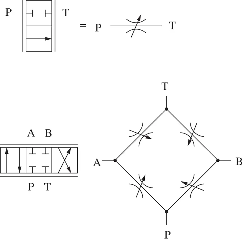
Figure 4.5 Hydraulic symbol of two valves and equivalent orifice networks.
The Eq. (4.9)points out how the effects due to the thermal expansion of the fluid can be neglected. This is a reasonable assumption for oils, which have a thermal expansion coefficient, α , typicall of 7 · 10 −4[1/ K ].
Assuming common properties for mineral based oil, the value of Δ T is approximately 5 to 6 degrees Celsius per 100 bar of pressure drop.
Example 4.1 Orifice Flow, Power Dissipation and Temperature Rise
An orifice is used in a pilot line of a system, connected to tank. The pressure in the line, upstream the orifice, is 190 bar , while the tank pressure is atmospheric. If the diameter of the orifice is D = 0.5 mm , evaluate the flow rate lost through it at maximum pressure and the power dissipated through it. Assume oil density ρ = 850 kg / m 3and C f= 0.62. If the constant specific heat of the oil is 1.8 kJ / kg K , estimate the temperature rise for the fluid across the orifice.
Given:
The pressure drop across the orifice Δ p OR= 190 bar ; the orifice diameter D = 0.5 mm ; the orifice coefficient C f= 0.62; the fluid density ρ = 850 kg / m 3and the specific heat coefficient c p= 1.8 kJ / kg K
Find:
1 the flow rate through the orifice QOR
2 the power dissipated by the orifice POR
3 temperature rise of the fluid through the orifice
Solution:
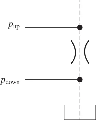
The ISO schematic of the system can be represented by the figure below. Note that the pilot line is represented as dashed line, according to the standard of representation.
1 QOR can be simply calculated by using the orifice equation (4.5), being the Δp across the orifice given by the problem data
2 The power dissipated is calculated from Eq. (4.8):
3 The temperature rise experienced by the fluid through the orifice can be estimated from Eq. (4.9), under the assumption that the entire heat dissipation increases the internal energy of the fluid
4.4 Parallel and Series Connections of Orifices
In some hydraulic circuits, orifices appear in series or in parallel configuration ( Figure 4.6). In these cases, it can be useful to evaluate the overall behavior of the system of orifices.
One way to address this problem is to consider the definition of hydraulic resistance for an orifice. Then, consider that
(4.10) 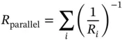
and
(4.11) 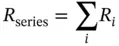
where the hydraulic resistance of the orifice has the expression of Eq. (4.7).
From Eqs. (4.10)and (4.11), the area of the equivalent orifice can be calculated. Another way for determining the area of the equivalent orifice is to directly derive the relationship between Q and Δ p of the set of orifices, as shown in the figure.
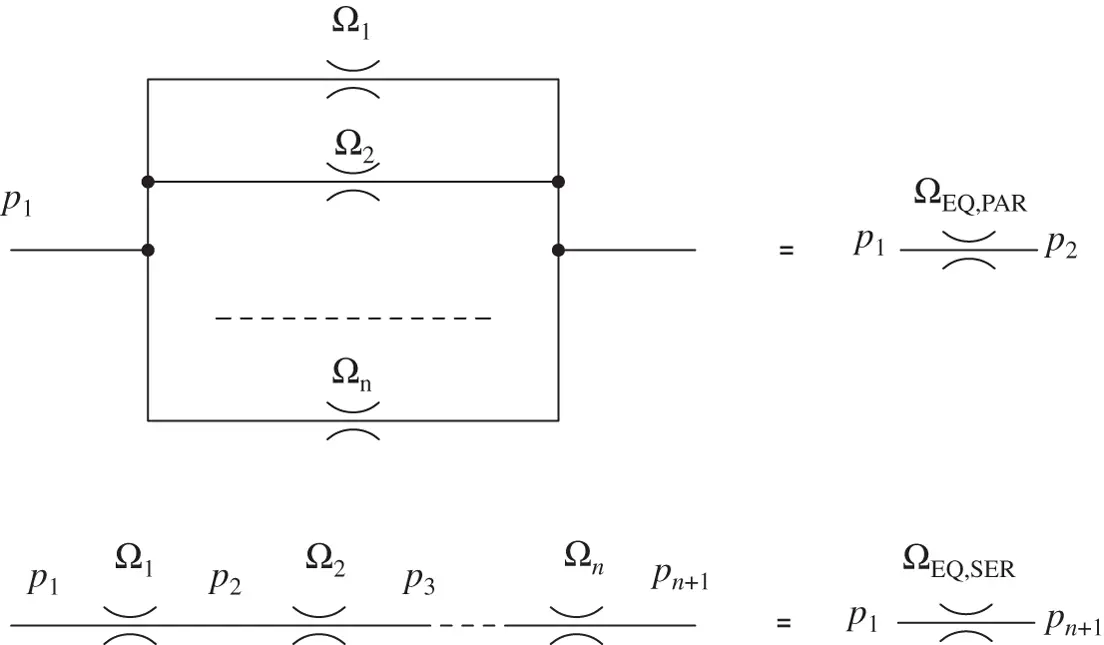
Figure 4.6 Orifice in parallel and in series.
For orifices connected in parallel, the overall flow is the sum of the individual flows, while the upstream and downstream pressures are equal for all:
(4.12) 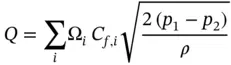
Therefore, if the same flow coefficient is assumed for all orifices, the area of the equivalent orifice is represented by the sum of the individual areas, and the equivalent diameter is square root of the sum of the square of the individual diameters:
(4.13) 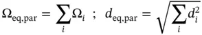
For orifices in series, the flow across the orifices is constant, while the Δ p at each orifice is different:
(4.14) 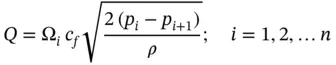
By definition, the equivalent orifice satisfies the equation:
(4.15) 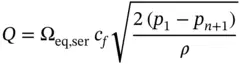
By equating the last two equations, it is possible to provide the expression for Ω eq, ser. This can be shown for the case of two orifices below, assuming again the same flow coefficient for all orifices:
(4.16) 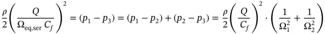
Therefore, the equivalent orifice area is
(4.17) 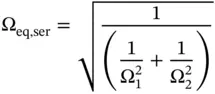
This equation can easily be generalized for more orifices:
(4.18) 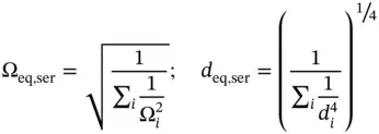
Example 4.2 Orifice Sizing
An emergency supply system uses an accumulator pressurized at 100 bar to extend a cylinder. This has a piston diameter D = 15 cm and sees a force of 50 kN . The connection between the cylinder and the accumulator is managed through a normally closed solenoid valve. The valve, when energized, implements a restriction equivalent to an orifice (this feature is represented in the valve symbol) with diameter of 4.4 mm and flow coefficient of 0.7. Assuming the accumulator is large enough to maintain a constant supply pressure, calculate the cylinder extension speed. Elaborate a simple system modification (without changing any of the existing components) for reducing the extension velocity to 60% of the previous value. Assume the pressure of the accumulator constant during the cylinder extension.
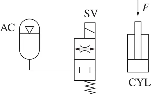
Given:
The ISO schematic of the hydraulic emergency system, which includes an accumulator as energy source, an on/off valve, and a linear actuator. The upstream pressure of the accumulator, constant, p acc= 100 bar ; the orifice diameter d 0= 4.4 mm and the flow coefficient C f= 0.7. The load on the actuator is F = 50 kN and the piston diameter, D = 15 cm .
Читать дальшеИнтервал:
Закладка:
Похожие книги на «Hydraulic Fluid Power»
Представляем Вашему вниманию похожие книги на «Hydraulic Fluid Power» списком для выбора. Мы отобрали схожую по названию и смыслу литературу в надежде предоставить читателям больше вариантов отыскать новые, интересные, ещё непрочитанные произведения.


Обсуждение, отзывы о книге «Hydraulic Fluid Power» и просто собственные мнения читателей. Оставьте ваши комментарии, напишите, что Вы думаете о произведении, его смысле или главных героях. Укажите что конкретно понравилось, а что нет, и почему Вы так считаете.