Andrea Vacca - Hydraulic Fluid Power
Здесь есть возможность читать онлайн «Andrea Vacca - Hydraulic Fluid Power» — ознакомительный отрывок электронной книги совершенно бесплатно, а после прочтения отрывка купить полную версию. В некоторых случаях можно слушать аудио, скачать через торрент в формате fb2 и присутствует краткое содержание. Жанр: unrecognised, на английском языке. Описание произведения, (предисловие) а так же отзывы посетителей доступны на портале библиотеки ЛибКат.

- Название:Hydraulic Fluid Power
- Автор:
- Жанр:
- Год:неизвестен
- ISBN:нет данных
- Рейтинг книги:3 / 5. Голосов: 1
-
Избранное:Добавить в избранное
- Отзывы:
-
Ваша оценка:
Hydraulic Fluid Power: краткое содержание, описание и аннотация
Предлагаем к чтению аннотацию, описание, краткое содержание или предисловие (зависит от того, что написал сам автор книги «Hydraulic Fluid Power»). Если вы не нашли необходимую информацию о книге — напишите в комментариях, мы постараемся отыскать её.
Readers of
will benefit from:
Approaching hydraulic fluid power concepts from an “outside-in” perspective, emphasizing a problem-solving orientation Abundant numerical examples and end-of-chapter problems designed to aid the reader in learning and retaining the material A balance between academic and practical content derived from the authors’ experience in both academia and industry Strong coverage of the fundamentals of hydraulic systems, including the equations and properties of hydraulic fluids
is perfect for undergraduate and graduate students of mechanical, agricultural, and aerospace engineering, as well as engineers designing hydraulic components, mobile machineries, or industrial systems.
Hydraulic Fluid Power — читать онлайн ознакомительный отрывок
Ниже представлен текст книги, разбитый по страницам. Система сохранения места последней прочитанной страницы, позволяет с удобством читать онлайн бесплатно книгу «Hydraulic Fluid Power», без необходимости каждый раз заново искать на чём Вы остановились. Поставьте закладку, и сможете в любой момент перейти на страницу, на которой закончили чтение.
Интервал:
Закладка:

which means that the x‐component of the force acting on the bolts is:
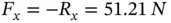
y‐component : With the assumption of no frictional forces, and considering that the exit section A 1is in atmosphere (gage pressure is null):

Due to gravity, the body force is given by the weight of the fluid inside the CV:
The second term of the y‐component of the momentum equation can be written under the same assumption of uniform flow, and considering that vertical components of the velocity at the control surface are present only at the section A 2:
Overall,


which means that the y‐component of the force acting on the bolts is
The orientation of the force on the bolts is therefore similar to the one indicated in the image above, with a horizontal component more pronounced than the vertical one.
3.8.1 Flow Forces
Another important application of the momentum equation is for the determination of the so‐called flow forces in hydraulic control valves.
The flow forces act on the moving element (generally a spool or a poppet) of the valve, and they are generated by the flow through the component. As it will be mentioned in Chapter 8, the presence of flow forces can significantly affect the operation of hydraulic control valves as well as the design of the valve actuation mechanism.
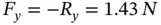
To understand the nature of flow forces and derive an analytical expression that can be useful to study most of the typical geometries of hydraulic control valves, the simplified case in Figure 3.17is taken as reference. The figure represents a spool that varies the valve opening between the pump (1) supply and the work port (2). Specifically, the spool can move horizontally along the x axis, and in the position represented in the figure, it determines an effective opening area between the valve ports respectively at the sections indicated in figure with 1 (inflow) and 2 (outflow).
The figure considers the common situation of A 1≫ A 2so that, per the conservation of mass, higher exit velocities are obtained. This is a very typical working condition of many hydraulic control valves, when low flow areas are implemented to regulate the actuator speed. The figure clearly shows how the flow changes its velocity and direction (therefore, its momentum) as it crosses the valve. Most of this momentum change is caused by the spool itself. The important question to be answered is: what is the force acting on the spool because of this momentum change? The answer is very important to understand how to size the valve actuation system, namely, the system that sets the position of the spool, which can be manually operated, electrically operated, or hydraulically operated. More details on the valve actuation systems will be provided in Chapter 8.
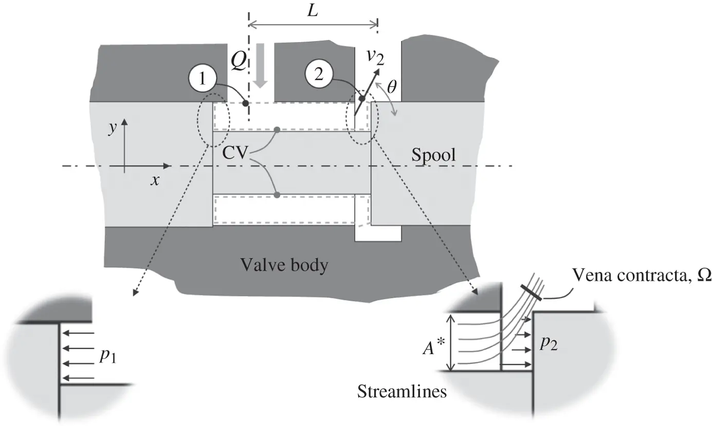
Figure 3.17 Reference geometry for the analysis of flow forces.
One possible way to answer this question consists in solving the pressure distribution at the spool walls, which is qualitatively shown in Figure 3.17. This approach requires a proper differential flow approach of analysis, where the governing equations are written for a differential fluid element and numerically integrated by mean of a computational fluid dynamics (CFD) tools. Numerical CFD techniques also allows studying more complex geometries that sometimes occurs in modern hydraulic control valves. However, the numerical CFD analysis can be time consuming, and it does not provide an analytical expression of the flow force. This analytical expression can be very useful to the valve designer to gain an intuitive understanding of the development of the flow forces, and more importantly it can be used if to formulate the proper controller parameters in case of hydraulic control valves using closed‐loop controls.
An analytical expression can be easily calculated applying the momentum equation to a properly selected CV. By considering the annular shaped CV indicated in Figure 3.17, with constant fluid density, the equation becomes
(3.44) 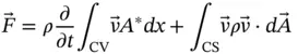
Assuming uniform flow at both inlet and outlet sections,
(3.45) 
where  and
and  are the unit vectors, respectively, along the horizontal and vertical directions. For a rigorous application of the momentum Eq. (3.43), the CV extends outward from the spool exit section A 2, until the vena contraction, Ω. This section is defined when the flow is mono‐dimensional (1D), which means parallel velocity streamlines. Only at Ω the uniform flow assumption is valid to describe the flow exiting the CV.
Therefore, from Eq. (3.44),
(3.46) 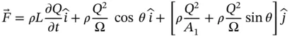
The objective of the flow force analysis usually corresponds to the force acting along the direction of motion of the moving element (in this case, the horizontal axis). This is the force that the actuation mechanism has to counter‐react to balance the spool. The vertical force is usually compensated through symmetric design of the spool and housing. For example, in this case, a second exit area would be typically present in the lower end of the spool. Therefore, for the case in Figure 3.17, the attention is focused on the horizontal component of Eq. (3.46):
(3.47) 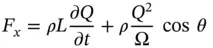
The term F xcorresponds to the forces acting on the CV through the CS. These include the pressure forces on the inlet and outlet sections, the pressure forces at the walls, and the frictional forces due to fluid shear. The pressure forces at both sections 1 and 2 can be considered as vertical 3 , and typically the effects of the fluid shear inside the valve is negligible when compared to the flow forces. For this reason, the above expression (3.47)summarizes all the forces that the walls exert on the fluid inside the CV.
Читать дальшеИнтервал:
Закладка:
Похожие книги на «Hydraulic Fluid Power»
Представляем Вашему вниманию похожие книги на «Hydraulic Fluid Power» списком для выбора. Мы отобрали схожую по названию и смыслу литературу в надежде предоставить читателям больше вариантов отыскать новые, интересные, ещё непрочитанные произведения.


Обсуждение, отзывы о книге «Hydraulic Fluid Power» и просто собственные мнения читателей. Оставьте ваши комментарии, напишите, что Вы думаете о произведении, его смысле или главных героях. Укажите что конкретно понравилось, а что нет, и почему Вы так считаете.