Liquid Biofuels
Здесь есть возможность читать онлайн «Liquid Biofuels» — ознакомительный отрывок электронной книги совершенно бесплатно, а после прочтения отрывка купить полную версию. В некоторых случаях можно слушать аудио, скачать через торрент в формате fb2 и присутствует краткое содержание. Жанр: unrecognised, на английском языке. Описание произведения, (предисловие) а так же отзывы посетителей доступны на портале библиотеки ЛибКат.
- Название:Liquid Biofuels
- Автор:
- Жанр:
- Год:неизвестен
- ISBN:нет данных
- Рейтинг книги:3 / 5. Голосов: 1
-
Избранное:Добавить в избранное
- Отзывы:
-
Ваша оценка:
Liquid Biofuels: краткое содержание, описание и аннотация
Предлагаем к чтению аннотацию, описание, краткое содержание или предисловие (зависит от того, что написал сам автор книги «Liquid Biofuels»). Если вы не нашли необходимую информацию о книге — напишите в комментариях, мы постараемся отыскать её.
provides a profound knowledge to researchers about biofuel technologies, selection of raw materials, conversion of various biomass to biofuel pathways, selection of suitable methods of conversion, design of equipment, selection of operating parameters, determination of chemical kinetics, reaction mechanism, preparation of bio-catalyst: its application in bio-fuel industry and characterization techniques, use of nanotechnology in the production of biofuels from the root level to its application and many other exclusive topics for conducting research in this area.
Written with the objective of offering both theoretical concepts and practical applications of those concepts,
can be both a first-time learning experience for the student facing these issues in a classroom and a valuable reference work for the veteran engineer or scientist. The description of the detailed characterization methodologies along with the precautions required during analysis are extremely important, as are the detailed description about the ultrasound assisted biodiesel production techniques, aviation biofuels and its characterization techniques, advance in algal biofuel techniques, pre-treatment of biomass for biofuel production, preparation and characterization of bio-catalyst, and various methods of optimization.
The book offers a comparative study between the various liquid biofuels obtained from different methods of production and its engine performance and emission analysis so that one can get the utmost idea to find the better biofuel as an alternative fuel. Since the book covers almost all the field of liquid biofuel production techniques, it will provide advanced knowledge to the researcher for practical applications across the energy sector.
A valuable reference for engineers, scientists, chemists, and students, this volume is applicable to many different fields, across many different industries, at all levels. It is a must-have for any library.
Liquid Biofuels — читать онлайн ознакомительный отрывок
Ниже представлен текст книги, разбитый по страницам. Система сохранения места последней прочитанной страницы, позволяет с удобством читать онлайн бесплатно книгу «Liquid Biofuels», без необходимости каждый раз заново искать на чём Вы остановились. Поставьте закладку, и сможете в любой момент перейти на страницу, на которой закончили чтение.
Интервал:
Закладка:
In the pyrolysis process, the most important process variables can be considered as heating speed, temperature and duration of stay. Those variables have the effect of reactor type and particle size on the heating speed. By using any type of reactor, if the particle size is increased, thermal conductivity decreases in the plant structure, heating rate decreases in the particle and changes in product yields occur. For each selected particle size, the reactor type acts on the mechanism of heat transfer. In other words, radiation, convection and conduction mechanisms vary depending on the type of the reactor [46].
Heating of biomass at low temperatures, long gas and solid retention time are called slow or conventional pyrolysis. Depending on the system, the heating rate is in the range of 0.1–2 °C per second and commonly the pyrolysis temperature is about 500 °C. The retention time of the gas can vary from 5 seconds to minutes or days, depending on the biomass. With conventional pyrolysis, approximately equal amounts of gas, liquid and solid products are obtained [47].
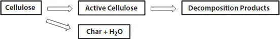
Figure 1.2 Multistep collective mechanism in the degradation of cellulose [47].
Fast pyrolysis is a high-temperature process in which biomass is rapidly heated in an oxygen-free environment. Heating rate is in the range of 200 and 105 °C/s and pyrolysis temperature is generally higher than 550 °C. The liquid obtained as a result of fast pyrolysis constitutes approximately 70-80% of the biomass. Fast pyrolysis is the most preferred pyrolysis method today for the production of liquid products with features such as low cost, easier transportation and storage [48].
1.4.2 Types of Reactors Used in Pyrolysis
Reactor type is effective on the composition and yield of the products obtained, and constitutes approximately 10-15% of the total cost of an integrated pyrolysis system. Pyrolysis reactors include reactor bed types such as fixed bed, fluid and suspended bed, movable bed, free fall feed reactor, inclined rotating oven, etc. [58]. Reactors such as circulating fluidized bed, ablative, bubbling fluidized bed, rotating cone, wire mesh braided and drag flow reactor are some of the types of pyrolysis reactors used today [59, 60]. In Table 1.2, the yield of biofuels obtained under different conditions from different types of reactors is indicated. As can be seen, lignocellulosic material and the process temperature have high effects on biofuel yield corresponding to the reactor type.
1.4.2.1 Bubble Fluidized Bed Reactor
Compared to other reactors, the design and construction of fluidized bed reactors is simpler. It has many advantages, such as good gas solid contact, excellent heat transfer properties, better temperature control and large heat storage capacity. Fluid bed pyrolysis offers good and consistent performance from wood, usually with a high liquid product efficiency of 60-75% by weight [58].
1.4.2.2 Circulating Fluidized Bed and Transport Bed Reactor
Circulating fluidized bed pyrolysis reactors have similar properties as bubble pyrolysis reactors. Compared to the bubbling fluidized bed pyrolysis reactor, steam and char are formed faster due to higher gas velocities. Thus, the char content in bio-oil is higher. Circulating fluidized bed pyrolysis reactor should provide higher process capacity, better gas solid contact [59].
Table 1.2 Types of reactors used in pyrolysis.
| Reactor Type | Biomass | Temperature (°C) | Pressure (atm) | Biofuel Yield (%) | Reference |
|---|---|---|---|---|---|
| Circulating fluidized bed | Wood chips | 250 | 138 | 49.9 | [61] |
| Tubular quartz | Arthrospira platensis | 450 | NA | 29.9 | [62] |
| Circulating fluid bed reactor | Lignocellulosic biomass | 400-600 | 1.6-3.3 | 72 | [63] |
| Stirred semi-batch reactor | Municipal plastic wastes | 400 | 1 | 76 | [64] |
| Fluidized bed reactor | Coal and beechwood | 600 | NA | 46 | [65] |
| Double auger reactor | Hardwood | 1061 | NA | 62 | [66] |
| Downer fluidizer bed reactor | Lignocellulosic biomass | 500 | 1 | 49.9 | [67] |
| Spouted bed reactor | Lignocellulosic biomass | 450 | NA | 58.7 | [68] |
1.4.2.3 Ablative Pyrolysis Reactor
The heat transferred from the hot reactor wall softens the raw material it contacts with under pressure. Pyrolysis moves in one direction between the biomass particles. Since the raw material is mechanically pushed forward, the remaining liquid film creates lubrication for the biomass particles. It also evaporates quickly to collect pyrolysis vapors. Pressure significantly affects the reaction rate. The advantages of the ablative pyrolysis reactor are that the particles create high pressure on the hot reactor wall due to the high relative motion and mechanical strength between the particle and the reactor wall [58].
1.4.2.4 Rotary Cone Reactor
Gas-solid contact was provided in the rotating conical reactor. At room temperature, biomass particles and hot sand particles are contacted near the bottom of the cone when the solids are mixed and carried up by the rotational motion of the cone. In such reactors, rapid heating and short gas retention time should be provided. Pressure is just above atmospheric levels. The initially entrained biomass enters the reactor superficially so that the particles are centrifuged against the cyclone wall, which is electrically heated to 1000 °C [59].
1.4.3 Chemical Conversion
Basically, acid hydrolysis of hexoses, pentoses and lignin is called chemical conversion processes. Various studies are carried out on the transformation of biomass with chemical processes. Hydrolysis reactions of biomass with enzymes are rather slow compared to hydrolysis reactions with acids. Acids used in hydrolysis process are examined in two parts. The first is hydrolysis in dilute acid medium, and the second is hydrolysis using sulfuric acid [69]. In Table 1.3, the yield of biofuels obtained under different chemicals and different biomass are indicated.
1.4.4 Electrochemical Conversion
Biomass can be converted into electrical energy by electrochemical (electrocatalytic) oxidation of the material. This can be performed in a carbon fuel cell, using an ethanol fuel cell, a methanol fuel cell and a microbial fuel cell. Fuel can also be consumed indirectly through a fuel cell system that includes a reformer that converts biomass into a mixture of CO and H 2before being consumed in the fuel cell [78].
Table 1.3 Biofuels as a result of chemical conversion of different chemicals and different biomass.
| Biomass | Reactor Type | Temperature (°C) | Chemical | Biofuel Yield (%) | Reference |
|---|---|---|---|---|---|
| Tea factory waste | Fixed bed | 400-700 | KOH | 24.7 | [70] |
| Chlorella pyrenoidosa | Mini autoclave | 400 | Freshly deionized water | 43.8 | [71] |
| Soybean oil | 5L home-made reactor | 40 | SnO | 60 | [72] |
| Pinewood | Autoclave | 280 | Pt/C | 33 | [73] |
| Empty fruit bunches | Autoclave | 300 | Metal chloride | 22.8 | [74] |
| Sugarcane bagasse | Discover microwave reactor | 80 | DMA-LiCl | 42 | [75] |
| Microalgae (methyl palmitate) | Batch reactor | 390 | Ni/meso-Y zeolite | 64.8 | [76] |
| Microalgae | Glass reactor | 62 | Sn | 16 | [77] |
1.4.5 Biochemical Methods
Интервал:
Закладка:
Похожие книги на «Liquid Biofuels»
Представляем Вашему вниманию похожие книги на «Liquid Biofuels» списком для выбора. Мы отобрали схожую по названию и смыслу литературу в надежде предоставить читателям больше вариантов отыскать новые, интересные, ещё непрочитанные произведения.


Обсуждение, отзывы о книге «Liquid Biofuels» и просто собственные мнения читателей. Оставьте ваши комментарии, напишите, что Вы думаете о произведении, его смысле или главных героях. Укажите что конкретно понравилось, а что нет, и почему Вы так считаете.