Anand K. Verma - Introduction To Modern Planar Transmission Lines
Здесь есть возможность читать онлайн «Anand K. Verma - Introduction To Modern Planar Transmission Lines» — ознакомительный отрывок электронной книги совершенно бесплатно, а после прочтения отрывка купить полную версию. В некоторых случаях можно слушать аудио, скачать через торрент в формате fb2 и присутствует краткое содержание. Жанр: unrecognised, на английском языке. Описание произведения, (предисловие) а так же отзывы посетителей доступны на портале библиотеки ЛибКат.

- Название:Introduction To Modern Planar Transmission Lines
- Автор:
- Жанр:
- Год:неизвестен
- ISBN:нет данных
- Рейтинг книги:4 / 5. Голосов: 1
-
Избранное:Добавить в избранное
- Отзывы:
-
Ваша оценка:
Introduction To Modern Planar Transmission Lines: краткое содержание, описание и аннотация
Предлагаем к чтению аннотацию, описание, краткое содержание или предисловие (зависит от того, что написал сам автор книги «Introduction To Modern Planar Transmission Lines»). Если вы не нашли необходимую информацию о книге — напишите в комментариях, мы постараемся отыскать её.
rovides a comprehensive discussion of planar transmission lines and their applications, focusing on physical understanding, analytical approach, and circuit models
Planar transmission lines form the core of the modern high-frequency communication, computer, and other related technology. This advanced text gives a complete overview of the technology and acts as a comprehensive tool for radio frequency (RF) engineers that reflects a linear discussion of the subject from fundamentals to more complex arguments.
Introduction to Modern Planar Transmission Lines: Physical, Analytical, and Circuit Models Approach Emphasizes modeling using physical concepts, circuit-models, closed-form expressions, and full derivation of a large number of expressions Explains advanced mathematical treatment, such as the variation method, conformal mapping method, and SDA Connects each section of the text with forward and backward cross-referencing to aid in personalized self-study
is an ideal book for senior undergraduate and graduate students of the subject. It will also appeal to new researchers with the inter-disciplinary background, as well as to engineers and professionals in industries utilizing RF/microwave technologies.
Introduction To Modern Planar Transmission Lines — читать онлайн ознакомительный отрывок
Ниже представлен текст книги, разбитый по страницам. Система сохранения места последней прочитанной страницы, позволяет с удобством читать онлайн бесплатно книгу «Introduction To Modern Planar Transmission Lines», без необходимости каждый раз заново искать на чём Вы остановились. Поставьте закладку, и сможете в любой момент перейти на страницу, на которой закончили чтение.
Интервал:
Закладка:
It is interesting to note that the velocity of EM‐wave and the characteristic ( intrinsic ) impedance of the free space are given in terms of these primary constants,
(4.1.8) 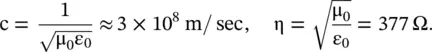
A material medium with a finite conductivity dissipates energy in the form of heat. The finite conductivity of a medium is due to the presence of free charge carriers . The free space is considered as a lossless medium because it has no free charge carrier. The conduction current flows through a medium under the influence of an external electric field. The conduction current density (  ) in a medium is related to the electric field intensity (
  ) by Ohm’s law :
(4.1.9) 
where σ is the conductivity of a conducting medium. The conductivity (σ) of the isotropic conducting medium is a scalar and for an anisotropic conducting medium it is a tensor. As free space has no conductivity, there is nothing like the relative conductivity of a medium. However, sometimes the conductivity of a medium is expressed in terms of the conductivity of copper.
In summary, the electrical properties of a material are described by the relative permittivity (ε r), relative permeability (μ r), and conductivity (σ). A material can have all three properties at a time, or it can have one predominant property at a time. Assuming the case of one predominant property at a time, all materials are classified into three basic categories.
4.1.3 Category of Materials
Dielectric Materials
The dielectric materials support electric polarization of bound charges and electric displacement current through it. At the micro‐level, the electric polarization creates dipole moments that appear as the permittivity of the dielectric material at the macro‐level . The permittivity is frequency‐dependent and lossy. So, permittivity is a complex quantity showing the lossy nature of dielectric materials. This is discussed in chapter 6. The relative permittivity of natural dielectric material is always positive and more than unity. However, engineered artificial dielectrics can have relative permittivity 0 < ε r< 1. Such materials are known as the epsilon near zero (ENZ) materials. Under certain conditions, it can also acquire negative permittivity, creating the epsilon negative (ENG) medium [B.16]. It is discussed in section (5.5)of chapter 5.
The electric displacement current flowing through a dielectric medium does not involve the flow of current through free charges. It is associated with time‐dependent electric fields. The electric displacement current density is a vector quantity. It expressed as follows:
(4.1.10) 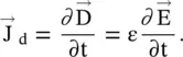
Magnetic Materials
The magnetic materials support magnetization, i.e. magnetic polarization by the magnetic field. It also supports magnetic displacement current due to the time‐dependent magnetic field:
(4.1.11) 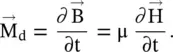
A diamagnetic material has permeability μ ≤ μ 0and a paramagnetic material has permeability μ > μ 0. The diamagnetic behavior is caused by induced magnetic dipole moments, creating a magnetic field that opposes the externally applied magnetic field. However, the paramagnetic property comes into existence due to the alignment of already randomly existing magnetic dipole moments in the material. The conducting ferromagnetic materials have much larger permeability due to domain formation. However, the engineered artificial magnetic materials can have relative permeability less than unity, 0 < μ r< 1. These are known as the mu near‐zero (MNZ) materials [B.16]. Again, the engineered materials can also have mu negative, giving the mu negative (MNG) materials . It is discussed in section (5.5)of chapter 5.
Conductors
It supports the flow of the free charge carrier, i.e. electrons. The free charge carriers are responsible for the conduction current density. It is given by equation (4.1.9). The free electrons confined within a neutral conductor form the plasma medium . The artificial dielectrics, including the wire‐medium (i.e. rodded medium), are also modeled as the plasma medium. The ionosphere also supports the plasma medium [B.2]. The plasma medium is modeled using the Drude model, discussed in subsection (6.5.2) of chapter 6. The plasma medium provides a means to engineer materials with negative permittivity. These materials are called the epsilon negative materials, i.e. the ENG materials.
4.2 Electrical Property of Medium
Any material can be electrically characterized by the relative permittivity (ε r), relative permeability (μ r) and conductivity (σ), or resistivity (ρ). However, these electrical parameters are not constants for any given material. For instance, these are both temperature and frequency‐dependent. Also, these may not be uniform throughout the volume of a material. Further, the characterizing parameters may depend on the field intensity, the direction of the applied field, operating frequency, working temperature, and pressure. The parameters can also depend on the history of a medium. However, the static value of these parameters, at room temperature, is treated as constant. A special kind of material, called chiral material, requires another parameter called chirality, i.e. the handedness of materials for its characterization [B.13, B.17]. Several properties of the medium are described briefly in this section.
4.2.1 Linear and Nonlinear Medium
The relative permittivity (ε r) and the relative permeability (μ r) of a linear material do not depend on the magnitude of the electric or magnetic field intensity, respectively. However, for nonlinear materials, the relative permittivity and relative permeability are functions of the electric and magnetic field intensity, respectively, and expressed as ε r(E) and μ r(H). Thus, for an isotropic nonlinear medium, equation (4.1.7a)is written as
(4.2.1) 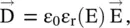
where ε r(E) = ε r1+ ε r2E + ε r3E 2+ ⋯ and so forth. The coefficients ε r2, ε r3, … indicate the order of nonlinearity in the nonlinear relative permittivity. In the case of a time‐harmonic electric field, i.e. E = E 0e jωt, equation (4.2.1)is written as,
(4.2.2) 
Интервал:
Закладка:
Похожие книги на «Introduction To Modern Planar Transmission Lines»
Представляем Вашему вниманию похожие книги на «Introduction To Modern Planar Transmission Lines» списком для выбора. Мы отобрали схожую по названию и смыслу литературу в надежде предоставить читателям больше вариантов отыскать новые, интересные, ещё непрочитанные произведения.


Обсуждение, отзывы о книге «Introduction To Modern Planar Transmission Lines» и просто собственные мнения читателей. Оставьте ваши комментарии, напишите, что Вы думаете о произведении, его смысле или главных героях. Укажите что конкретно понравилось, а что нет, и почему Вы так считаете.