Anand K. Verma - Introduction To Modern Planar Transmission Lines
Здесь есть возможность читать онлайн «Anand K. Verma - Introduction To Modern Planar Transmission Lines» — ознакомительный отрывок электронной книги совершенно бесплатно, а после прочтения отрывка купить полную версию. В некоторых случаях можно слушать аудио, скачать через торрент в формате fb2 и присутствует краткое содержание. Жанр: unrecognised, на английском языке. Описание произведения, (предисловие) а так же отзывы посетителей доступны на портале библиотеки ЛибКат.

- Название:Introduction To Modern Planar Transmission Lines
- Автор:
- Жанр:
- Год:неизвестен
- ISBN:нет данных
- Рейтинг книги:4 / 5. Голосов: 1
-
Избранное:Добавить в избранное
- Отзывы:
-
Ваша оценка:
Introduction To Modern Planar Transmission Lines: краткое содержание, описание и аннотация
Предлагаем к чтению аннотацию, описание, краткое содержание или предисловие (зависит от того, что написал сам автор книги «Introduction To Modern Planar Transmission Lines»). Если вы не нашли необходимую информацию о книге — напишите в комментариях, мы постараемся отыскать её.
rovides a comprehensive discussion of planar transmission lines and their applications, focusing on physical understanding, analytical approach, and circuit models
Planar transmission lines form the core of the modern high-frequency communication, computer, and other related technology. This advanced text gives a complete overview of the technology and acts as a comprehensive tool for radio frequency (RF) engineers that reflects a linear discussion of the subject from fundamentals to more complex arguments.
Introduction to Modern Planar Transmission Lines: Physical, Analytical, and Circuit Models Approach Emphasizes modeling using physical concepts, circuit-models, closed-form expressions, and full derivation of a large number of expressions Explains advanced mathematical treatment, such as the variation method, conformal mapping method, and SDA Connects each section of the text with forward and backward cross-referencing to aid in personalized self-study
is an ideal book for senior undergraduate and graduate students of the subject. It will also appeal to new researchers with the inter-disciplinary background, as well as to engineers and professionals in industries utilizing RF/microwave technologies.
Introduction To Modern Planar Transmission Lines — читать онлайн ознакомительный отрывок
Ниже представлен текст книги, разбитый по страницам. Система сохранения места последней прочитанной страницы, позволяет с удобством читать онлайн бесплатно книгу «Introduction To Modern Planar Transmission Lines», без необходимости каждый раз заново искать на чём Вы остановились. Поставьте закладку, и сможете в любой момент перейти на страницу, на которой закончили чтение.
Интервал:
Закладка:
Once the error boxes are characterized through their S‐parameters, it can be converted to the [A eB eC eD e] parameters. Similarly, the measured S‐parameters of the device and the error box combined are available at the external ports. These can be converted to the measured [A mB mC mD m] parameters. The device [A dB dC dD d] parameters are related to the other two parameters by the following equation:
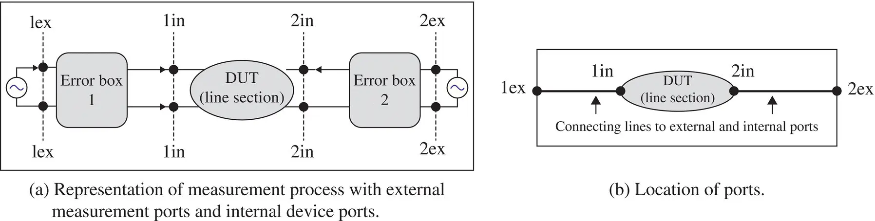
Figure 3.20 Calibration process in the measurement of S‐parameters of a device.
(3.2.21) 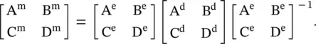
The error box 2 is the mirror image of the error box 1 with respect to the DUT. So in the above‐given matrix sequence, the third matrix is inverse of the first matrix [B.11]. At the internal device ports, the device [A dB dC dD d] parameters are de‐embedding as follows:
(3.2.22) 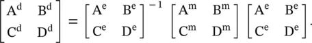
The de‐embedded device [A dB dC dD d] parameters are converted to the de‐embedded S‐parameters of the device. The de‐embedded S‐parameters could be further converted to the Z and Y‐parameters. Thus, any two‐port device can be characterized through measurements using suitable parameters‐ S, Z, or Y. In the case of a transmission line section, the de‐embedded S‐parameters can be converted to the propagation parameters and the characteristic impedance of the line.
The above‐mentioned concept of de‐embedding of the device S‐parameters at the internal port of a device is equally applicable to the EM‐Simulators – both 2.5D and 3D simulators [B.10]. In EM‐simulators, the delta‐gap voltage source could be used to launch the wave on a line section or a device. It also generates the nonpropagating evanescent modes at the ports. They cause a discontinuity at the external circuit ports, i.e. at the ports of simulation. The port discontinuity affects the S‐parameters of the device that is removed by the process of de‐embedding [J.2]. The EM‐simulators could be used to extract the propagation parameters and the characteristic impedance of a line.
3.2.3 Extraction of Propagation Characteristics
The true S‐parameters of the line section, i.e. its de‐embedded S‐parameters over a range of frequencies are known either through the measurement or through the EM‐simulation. This information can be converted to the [ABCD] parameters of a line section as follows [B.1]:
(3.2.23) 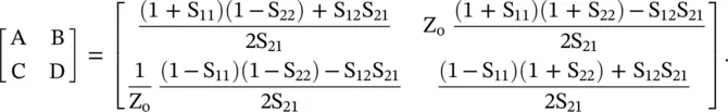
Usually, S 11= S 22and S 12= S 21because a section of the transmission line is treated as the symmetrical and reciprocal network. The frequency‐dependent [ABCD] parameters of a lossy line of length ℓ are used to compute the characteristic impedance Z 0and propagation constant γ = α + j β over a range of frequencies [B.1]:
(3.2.24) 
The frequency‐dependent secondary line parameters are extracted to get the dispersion characteristics of a line. Once the secondary line parameters of a line section are known, their frequency‐dependent primary constants are computed as follows:
(3.2.25) 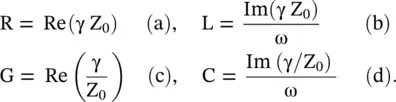
3.3 Wave Velocity on Transmission Line
In a communication network, several kinds of electrical signals propagate on a transmission line. The signal could be a modulated or unmodulated carrier wave, the baseband analog signal, or the digital pulses. The TEM mode transmission lines, and also various kinds of non‐TEM waveguide structures support wave propagation. The parameters defining these transmitting media could be either frequency‐independent or frequency‐dependent. The property of the medium has a significant impact on the nature of wave propagation through a medium. The wave velocity has no simple or unique meaning, like the meaning of the velocity of a particle. There are several kinds of wave velocities – phase velocity, group velocity, energy velocity, signal velocity, etc., applied to wave propagation. The significance of several types of wave velocities is inherent both in the complexity of a signal and also in the complexity of the wave supporting medium. This section focuses attention on the meaning of the phase and group velocities only. Section ( 3.4) demonstrates these two wave velocities as applied to several kinds of the artificial linear dispersive transmission lines .
3.3.1 Phase Velocity
The concept of phase velocity is applicable to a single frequency wave, i.e. to a monochromatic wave discussed in Section (2.1)of chapter 2. The phase velocity is just the movement of the wavefront . The wavefront is a surface of constant phase, like maximum, minimum, or zero‐level points shown in Fig (2.3). It is given by equation (2.1.8)of chapter 2and reproduced below:
(3.3.1) 
The propagation constant β is influenced by the wave‐supporting medium. For a lossless TEM transmission line and lossless unbounded space, β is given by
(3.3.2) 
where ε and μ are permittivity and permeability of a medium. Thus, pairs (L, C) and (ε, μ) are the parameters that characterize the electrical property of the wave supporting‐media. The unbounded medium supports the plane wave propagation. If these parameters are not frequency‐dependent, the medium is known as nondispersive . In such a medium, the phase velocity remains constant at every frequency. However, if any of these parameters are frequency‐dependent, the propagation constant β is frequency‐dependent and consequently, the phase velocity is frequency‐dependent. The medium that supports the frequency‐dependent phase velocity is known as the dispersive medium. Normally, the characteristic impedance or intrinsic impedance of a dispersive medium is also frequency‐dependent. The parameters (L, C) and (ε, μ) are usually independent of signal strength. Such a medium is called a linear medium, whereas the signal strength dependent medium is a nonlinear medium. The characteristics of the medium are discussed in Section ( 4.2) of chapter 4. The present discussion is only about the linear and dispersive transmission lines.
Why a medium becomes dispersive? One reason for dispersion is the loss associated with a medium. The geometry of a wave supporting inhomogeneous structures, commonly encountered in the planar technology, is another source of the dispersion. In the case of a transmission line, the parameters R and G are associated with losses and they make propagation constant β frequency‐dependent. Likewise, losses make permittivity ε and permeability μ of material medium frequency‐dependent complex quantities. However, a low‐loss dielectric medium can be nondispersive in the useful frequency band. For such cases, the attenuation and propagation constants are given by
Читать дальшеИнтервал:
Закладка:
Похожие книги на «Introduction To Modern Planar Transmission Lines»
Представляем Вашему вниманию похожие книги на «Introduction To Modern Planar Transmission Lines» списком для выбора. Мы отобрали схожую по названию и смыслу литературу в надежде предоставить читателям больше вариантов отыскать новые, интересные, ещё непрочитанные произведения.


Обсуждение, отзывы о книге «Introduction To Modern Planar Transmission Lines» и просто собственные мнения читателей. Оставьте ваши комментарии, напишите, что Вы думаете о произведении, его смысле или главных героях. Укажите что конкретно понравилось, а что нет, и почему Вы так считаете.