Joseph R. Badick - Flight Theory and Aerodynamics
Здесь есть возможность читать онлайн «Joseph R. Badick - Flight Theory and Aerodynamics» — ознакомительный отрывок электронной книги совершенно бесплатно, а после прочтения отрывка купить полную версию. В некоторых случаях можно слушать аудио, скачать через торрент в формате fb2 и присутствует краткое содержание. Жанр: unrecognised, на английском языке. Описание произведения, (предисловие) а так же отзывы посетителей доступны на портале библиотеки ЛибКат.
- Название:Flight Theory and Aerodynamics
- Автор:
- Жанр:
- Год:неизвестен
- ISBN:нет данных
- Рейтинг книги:4 / 5. Голосов: 1
-
Избранное:Добавить в избранное
- Отзывы:
-
Ваша оценка:
Flight Theory and Aerodynamics: краткое содержание, описание и аннотация
Предлагаем к чтению аннотацию, описание, краткое содержание или предисловие (зависит от того, что написал сам автор книги «Flight Theory and Aerodynamics»). Если вы не нашли необходимую информацию о книге — напишите в комментариях, мы постараемся отыскать её.
AERODYNAMICS
GET A PILOT’S PERSPECTIVE ON FLIGHT AERODYNAMICS FROM THE MOST UP-TO-DATE EDITION OF A CLASSIC TEXT Flight Theory and Aerodynamics
Flight Theory and Aerodynamics
Flight Theory and Aerodynamics
Flight Theory and Aerodynamics — читать онлайн ознакомительный отрывок
Ниже представлен текст книги, разбитый по страницам. Система сохранения места последней прочитанной страницы, позволяет с удобством читать онлайн бесплатно книгу «Flight Theory and Aerodynamics», без необходимости каждый раз заново искать на чём Вы остановились. Поставьте закладку, и сможете в любой момент перейти на страницу, на которой закончили чтение.
Интервал:
Закладка:
Consider the flow of air through a venturi tube as shown in Figure 2.6. In Image A, as the mass of air experiences a constriction in the tube and as the velocity of the mass increases, the pressure decreases. A comparative image of a wing experiencing Bernoulli’s principle during flight is in Image B. Note the decreased density toward the rear of the airfoil, this will be a discussion area in Chapters 3and 4.
The energy of an airstream is in two forms: It has a potential energy , which is its static pressure, and a kinetic energy , which is its dynamic pressure. The total pressure of the airstream is the sum of the static pressure and the dynamic pressure. The total pressure remains constant, according to the law of conservation of energy. Thus, an increase in one form of pressure must result in an equal decrease in the other.
Static pressure is an easily understood concept (see the discussion earlier in this chapter). Dynamic pressure, q , is similar to kinetic energy in mechanics and is expressed by
(2.9) 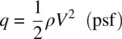
where V is measured in feet per second. Pilots are much more familiar with velocity measured in knots instead of in feet per second, so a new equation for dynamic pressure, q , is used in this book. Its derivation is shown here:

Figure 2.6 Pressure change in a venturi tube.
Source: U.S. Department of Transportation Federal Aviation Administration (2018).
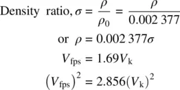
Substituting in Eq. 2.9yields
(2.10) 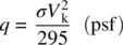
Bernoulli’s equation can now be expressed as
Total pressure (head pressure), H = Static pressure, P + Dynamic pressure, q :
(2.11) 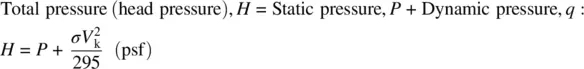
To visualize how lift is developed on a cambered airfoil, draw a line down the middle of a venturi tube. Discard the upper half of the figure and superimpose an airfoil on the constricted section of the tube ( Figure 2.7). Note that the static pressure over the airfoil is less than that ahead of it and behind it, so, as dynamic pressure increases, static pressure decreases.
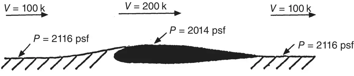
Figure 2.7 Velocities and pressures on an airfoil superimposed on a venturi tube.
AIRSPEED MEASUREMENT
If a symmetrically shaped object is placed in a moving airstream ( Figure 2.8), the flow pattern will be as shown. Some airflow will pass over the object and some will flow beneath it, but at the point at the nose of the object, the flow will be stopped completely. This point is called the stagnation point . Since the air velocity at this point is zero, the dynamic pressure is also zero. The stagnation pressure is, therefore, all static pressure and must be equal to the total pressure, H , of the airstream.
In Figure 2.9, the free stream values of velocity and pressure are used to measure the indicated airspeed of an aircraft. The pitot tube is shown as the total pressure port and must be pointed into the relative wind for accurate readings. Static pressure, sometimes referred to as ambient pressure, is the pressure around the aircraft whether it is moving or at rest, and is the same “local” pressure your body experiences. When in motion, the air entering the pitot tube comes to a complete stop and thus the static pressure in the tube is equal to the total free stream pressure, H . This pressure is ducted into a diaphragm inside the airspeed indicator.
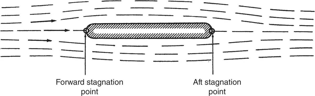
Figure 2.8 Flow around a symmetrical object.
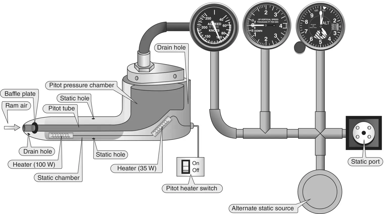
Figure 2.9 Schematic of a pitot–static airspeed indicator.
Source: U.S. Department of Transportation Federal Aviation Administration (2012c).
The static pressure port(s) can be made as a part of the point tube or it can be at a distance from the pitot tube on the side of the aircraft. It should be located at a point where the local air velocity is exactly equal to the airplane velocity. The static port is made so that none of the velocity enters the port. The port measures only static pressure, and none of the dynamic pressure. The static pressure is ducted into the chamber surrounding the diaphragm within the inside of the airspeed indicator.
Now we have static pressure inside the diaphragm that is equal to total pressure ( H ), and then static pressure measured from the static port outside the diaphragm. The difference between the pressure inside the diaphragm and outside the diaphragm is the differential pressure that deflects the flexible diaphragm that is geared to the airspeed pointer. The static pressures cancel each other, thus the dynamic pressure is left and indicated on the airspeed indicator. The airspeed indicator measures differential pressure. The airspeed indicator is calibrated to read airspeed.
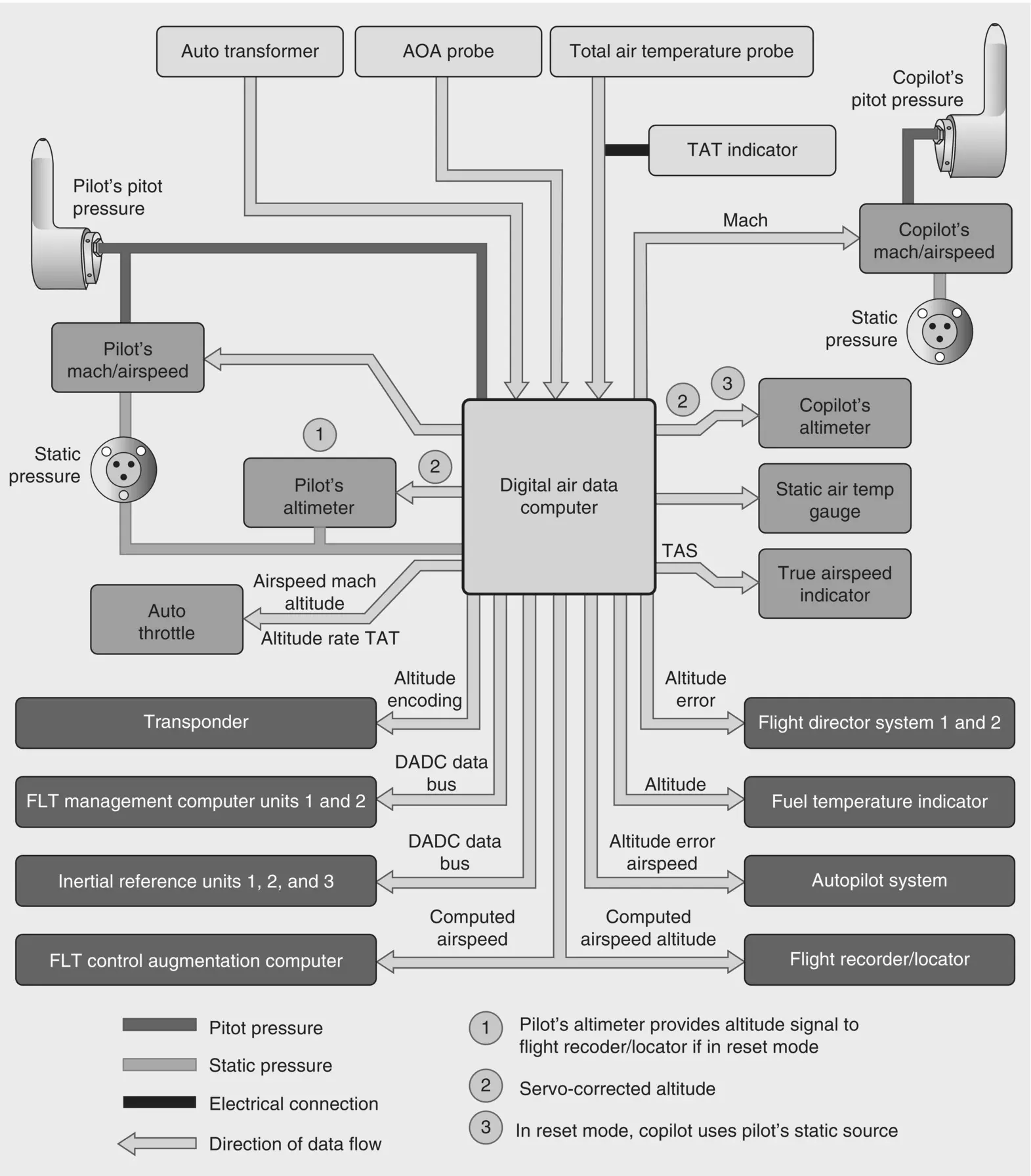
Figure 2.10 Air data computer and pitot–static sensing.
Source: U.S. Department of Transportation Federal Aviation Administration (2012a).
Figure 2.10shows a modern pitot–static system associated with an air data computer (ADC). Though the concept with this solid state device is the same as in traditional pitot–static systems, the signal sent to modern “glass” instruments is digital and often has the ability to generate trend vectors.
Application 2.3
Figure 2.11indicates the impact of a blockage of the pitot tube while an aircraft is flying at altitude. The resultant effect is that the airspeed indicator acts like an altimeter: as the aircraft climbs in altitude, the airspeed increases, and when the aircraft descends, the airspeed decreases.
In a traditional airspeed indicator with a diaphragm, what is happening in reference to our discussion on q , P , and H in the situation above? What is the impact of the blockage on the other pitot–static instruments? Why?
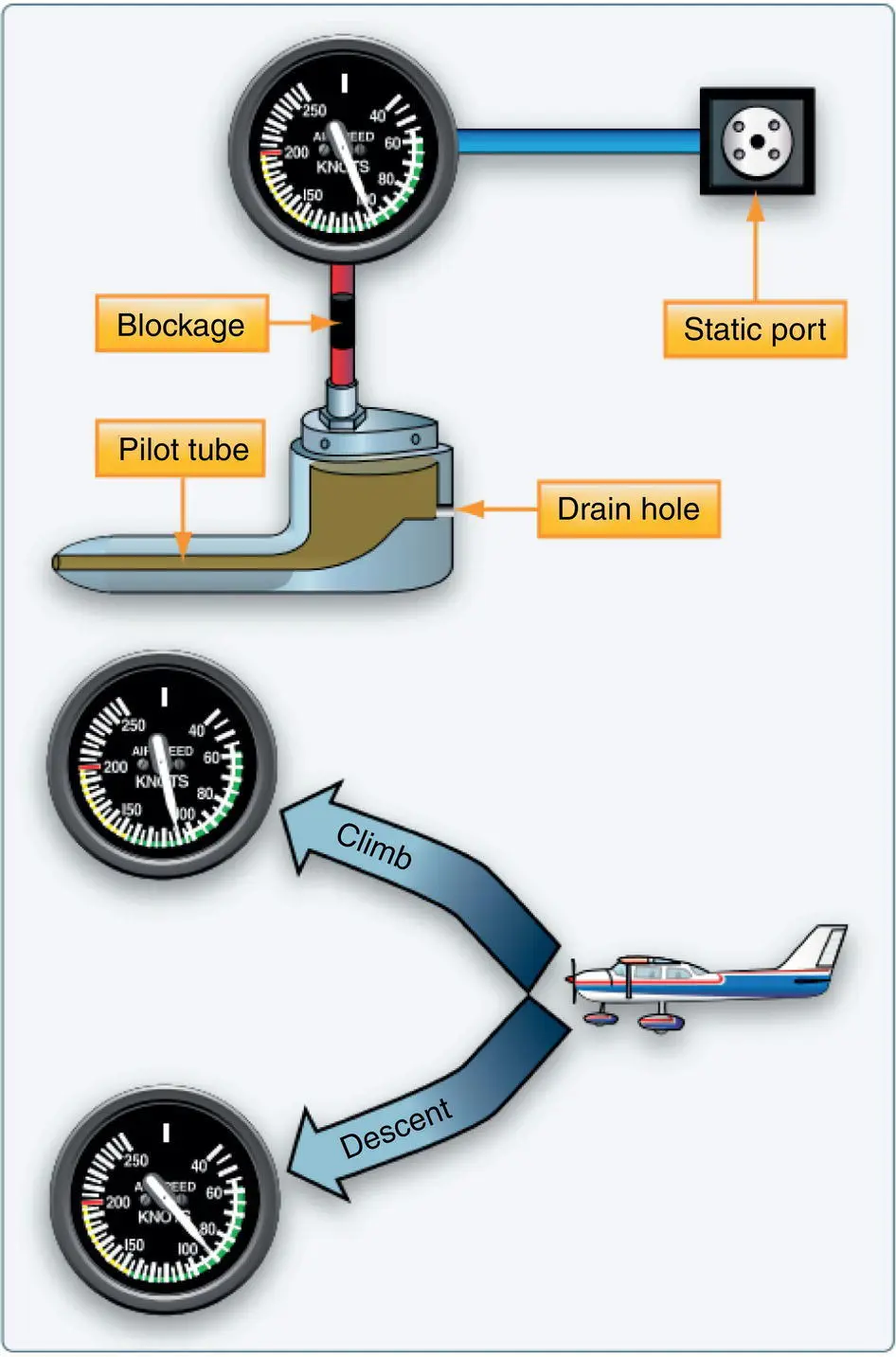
Figure 2.11 Blocked pitot tube and drain hole.
Source: U.S. Department of Transportation Federal Aviation Administration (2016b).
Читать дальшеИнтервал:
Закладка:
Похожие книги на «Flight Theory and Aerodynamics»
Представляем Вашему вниманию похожие книги на «Flight Theory and Aerodynamics» списком для выбора. Мы отобрали схожую по названию и смыслу литературу в надежде предоставить читателям больше вариантов отыскать новые, интересные, ещё непрочитанные произведения.


Обсуждение, отзывы о книге «Flight Theory and Aerodynamics» и просто собственные мнения читателей. Оставьте ваши комментарии, напишите, что Вы думаете о произведении, его смысле или главных героях. Укажите что конкретно понравилось, а что нет, и почему Вы так считаете.