Rodolfo Araneo - Electrical Safety Engineering of Renewable Energy Systems
Здесь есть возможность читать онлайн «Rodolfo Araneo - Electrical Safety Engineering of Renewable Energy Systems» — ознакомительный отрывок электронной книги совершенно бесплатно, а после прочтения отрывка купить полную версию. В некоторых случаях можно слушать аудио, скачать через торрент в формате fb2 и присутствует краткое содержание. Жанр: unrecognised, на английском языке. Описание произведения, (предисловие) а так же отзывы посетителей доступны на портале библиотеки ЛибКат.
- Название:Electrical Safety Engineering of Renewable Energy Systems
- Автор:
- Жанр:
- Год:неизвестен
- ISBN:нет данных
- Рейтинг книги:5 / 5. Голосов: 1
-
Избранное:Добавить в избранное
- Отзывы:
-
Ваша оценка:
Electrical Safety Engineering of Renewable Energy Systems: краткое содержание, описание и аннотация
Предлагаем к чтению аннотацию, описание, краткое содержание или предисловие (зависит от того, что написал сам автор книги «Electrical Safety Engineering of Renewable Energy Systems»). Если вы не нашли необходимую информацию о книге — напишите в комментариях, мы постараемся отыскать её.
A reference to designing and developing electrical systems connected to renewable energies Electrical Safety Engineering of Renewable Energy Systems
Electrical Safety Engineering of Renewable Energy Systems
Electrical Safety Engineering of Renewable Energy Systems — читать онлайн ознакомительный отрывок
Ниже представлен текст книги, разбитый по страницам. Система сохранения места последней прочитанной страницы, позволяет с удобством читать онлайн бесплатно книгу «Electrical Safety Engineering of Renewable Energy Systems», без необходимости каждый раз заново искать на чём Вы остановились. Поставьте закладку, и сможете в любой момент перейти на страницу, на которой закончили чтение.
Интервал:
Закладка:
The temperature limits of Table 1.8are rather large, and it would be prudent to be well below those values; if not possible, the equipment in question might be fitted with guards to prevent accidental contact.
1.6 Ground-Potential and Ground-Resistance
A ground electrode is a conductive part, embedded in the soil or in another conductive medium (e.g., concrete), which is in electrical contact with the earth [22].
A connection to the ground can also be made through metalwork not forming part of the electrical installation, such as structural steelwork, metal, water supply pipes, or other buried metalwork. Such metalwork, however, should not be relied upon as an electrode, as it could be removed or replaced without any warning to users. The safety purpose of ground-electrodes is to effectively dissipate fault-currents into the soil.
To illustrate the relationship between ground-potentials, ground-resistances, and ground-currents, we study a hemispherical electrode, as this will allow the understanding of the performance of electrodes of different geometry.
We consider a hemisphere of radius r0 embedded in a boundless and uniform soil of resistivity ρ , buried at a sufficient distance from a receiving electrode, and that the ground-current i leaking from this electrode flows radially into the soil (Figure 1.8).
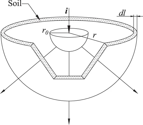
Figure 1.8 Hemispherical ground-electrode.
The current density J→, identified as a vector quantity, through a surface S in the soil of infinitesimal thickness dl , r from the center of the hemisphere, is related to the uniform leakage current i through the flux operator expressed in Eq. 1.5.
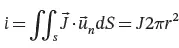 (1.5)
(1.5)
Equation 1.5yields:
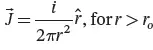 (1.6)
(1.6)
where r^ is the unit vector in the radial direction.
The electric field E→at any distance r from the center of the hemisphere can be determined as:
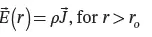 (1.7)
(1.7)
The ground-potential on the soil surface at any distance r from the center of the hemisphere, which is taken zero at infinity, is:
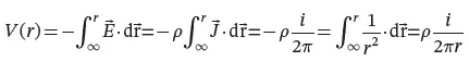 (1.8)
(1.8)
The ground-potential V(r) features a hyperbolic distribution through the soil, with the coordinate axes as asymptotes (Figure 1.9 ).
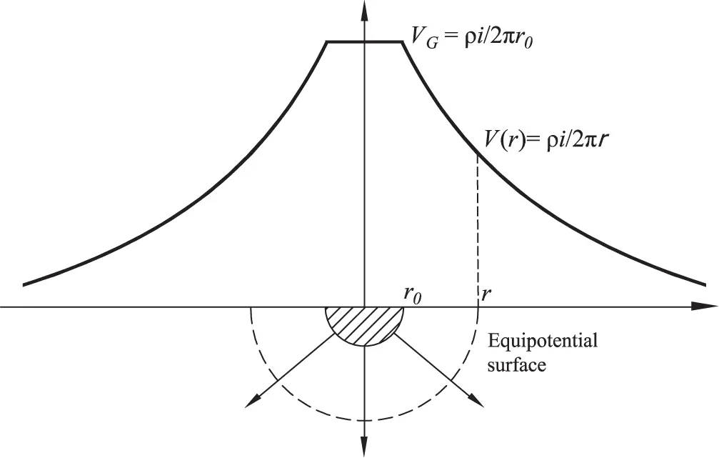
Figure 1.9 Hyperbolic distribution of the ground-potential V(r) over the soil.
The equipotential surfaces are hemispheres, including the actual surface of the electrode. Points belonging to the same equipotential surface have equal potential both on the surface and deep in the soil. Current lines are perpendicular to such surfaces.
The ground-potential rise on the surface of the hemisphere, that is, the potential at the distance r0 from its center, is
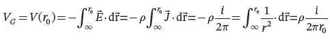 (1.9)
(1.9)
We define the resistance RG of the hemisphere-electrode to earth (from now on the ground-resistance ) as the ratio of the ground-potential rise VG to the leakage current i ( Eq. 1.10).
 (1.10)
The ground-resistance of a ground-electrode can be seen as an equivalent one-port (Figure 1.10): one terminal of the one-port is the metal connection to the electrode (generally named grounding electrode conductor in codes and standards), whereas the other terminal represents a point at zero potential (i.e., a point at sufficient distance from the electrode where the potential is negligible).
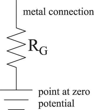
Figure 1.10 Electrode ground-resistance as an equivalent one-port.
The ground symbol (from IEC 60417 “ Graphical symbols for use on equipment ,” symbol 5017) does not represent the soil, but a point at sufficient distance from the electrode where the surface potential is negligible.
From the graph of the ground potential of Figure 1.9, it can be observed that the radius r0 of the hemisphere identifies the point from where the hyperbolic distribution starts. For a given hemisphere, different values of the product ρ i determine different hyperbolae, whose distance for the horizontal axis depends on the soil resistivity and the fault-current.
The rate-of-change of the potential with the distance r from the hemisphere (i.e., the potential gradient) is defined in Eq. 1.11.
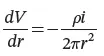 (1.11)
which shows that the maximum variation of the ground potential occurs in proximity of the hemispherical electrode (i.e. r ≈ r o).
1.6.1 Area of Influence of a Ground-electrode
The electric field is a long-range field and is zero only at infinite distance from its source, and so is the ground potential . In engineering practice, however, the design of ground electrodes is based on the area of influence , which defines the zone beyond which the ground potential can be considered negligible. If we evaluate the ground potential at the distance r = 5 r0 , we obtain:
 (1.12)
At a distance 5r 0from the center of the hemisphere, the ground potential reduces to 20% of the ground potential rise, and this result has a general validity, independently of the shape of the electrode. It can conventionally be assumed that the hemispherical volume of the earth of radius 5r 0is the area of influence of the electrode. For differently-shaped electrodes (e.g., rods, rings, grids, etc.), their maximum dimensions can be used in lieu of the radius; for instance, for grounding grids, the largest diagonal can be employed to identify the area of influence.
Two unconnected ground-electrodes are defined as independent from each other if they are outside of their respective areas of influence.
1.7 Hemispherical Electrodes in Parallel
Интервал:
Закладка:
Похожие книги на «Electrical Safety Engineering of Renewable Energy Systems»
Представляем Вашему вниманию похожие книги на «Electrical Safety Engineering of Renewable Energy Systems» списком для выбора. Мы отобрали схожую по названию и смыслу литературу в надежде предоставить читателям больше вариантов отыскать новые, интересные, ещё непрочитанные произведения.


Обсуждение, отзывы о книге «Electrical Safety Engineering of Renewable Energy Systems» и просто собственные мнения читателей. Оставьте ваши комментарии, напишите, что Вы думаете о произведении, его смысле или главных героях. Укажите что конкретно понравилось, а что нет, и почему Вы так считаете.