Polymer Composites for Electrical Engineering
Здесь есть возможность читать онлайн «Polymer Composites for Electrical Engineering» — ознакомительный отрывок электронной книги совершенно бесплатно, а после прочтения отрывка купить полную версию. В некоторых случаях можно слушать аудио, скачать через торрент в формате fb2 и присутствует краткое содержание. Жанр: unrecognised, на английском языке. Описание произведения, (предисловие) а так же отзывы посетителей доступны на портале библиотеки ЛибКат.
- Название:Polymer Composites for Electrical Engineering
- Автор:
- Жанр:
- Год:неизвестен
- ISBN:нет данных
- Рейтинг книги:5 / 5. Голосов: 1
-
Избранное:Добавить в избранное
- Отзывы:
-
Ваша оценка:
Polymer Composites for Electrical Engineering: краткое содержание, описание и аннотация
Предлагаем к чтению аннотацию, описание, краткое содержание или предисловие (зависит от того, что написал сам автор книги «Polymer Composites for Electrical Engineering»). Если вы не нашли необходимую информацию о книге — напишите в комментариях, мы постараемся отыскать её.
Polymer Composites for Electrical Engineering
Polymer Composites for Electrical Engineering
Polymer Composites for Electrical Engineering — читать онлайн ознакомительный отрывок
Ниже представлен текст книги, разбитый по страницам. Система сохранения места последней прочитанной страницы, позволяет с удобством читать онлайн бесплатно книгу «Polymer Composites for Electrical Engineering», без необходимости каждый раз заново искать на чём Вы остановились. Поставьте закладку, и сможете в любой момент перейти на страницу, на которой закончили чтение.
Интервал:
Закладка:
Table 2.4 Thermal conductivity of polymeric phase change composites.
| Material systems | Processing methods | Thermally conductive filler loading | Melting enthalpy (Jg −1) | Thermal conductivity (W m −1K −1) | Thermal conductivity enhancement (%) |
|---|---|---|---|---|---|
| PEG/diatomite/silver nanoparticle[84] | Vacuum impregnation | 7.2 wt% | 111.3 | 0.82 | 127 |
| PEG/EVM/silver nanowire[51] | Physical blending and impregnation | 19.3 wt% | 99.1 | 0.68 | 172 |
| PEG/SiO 2/cupper[85] | Sol–gel and in‐situ doping method | 2.1 wt% | 110.2 | 0.414 | 15 |
| PW/silver‐PVP nanowire aerogel[87] | Vacuum impregnation | 5.43 wt% | ∼163 | 0.49 | ∼133 |
| PEG‐co‐ N , N ′‐dihydroxyethyl aniline/single‐walled CNT[88] | Vacuum evaporation | — | 100.5 | 0.334 | 25 |
| PEG/single‐walled CNT[90] | Solution blending | 10 wt% | 165.4 | 3.43 | 1329 |
| PEG/SiO 2/CF[91] | Sol–gel and in‐ situ doping method | 3 wt% | 142.6 | 0.45 | 73 |
| PEG/EG[54] | Melt blending | 10 wt% | 161.2 | 1.324 | 344 |
| PEG/GO/GNP[92] | Solution blending | 6 wt% | 167.4 | 1.72 | 493 |
| PEG/unsaturated polyester resin/GNP[93] | Free radical copolymerization and solution blending | 2 wt% | 140.8 | 0.67 | 131 |
| PEG/single‐walled CNT[89] | Vacuum impregnation | 8 wt% | 162.1 | 2.73 | 950 |
| PEG/GNP[89] | Vacuum impregnation | 4 wt% | 169.3 | 3.11 | 1096 |
| Poly(hexadecyl acrylate)/cellulose/graphene[94] | Atom transfer radical polymerization (ATRP) and injection molding | 9 wt% | 78 | 1.32 | 560 |
| PEG/biological porous carbon[16] | Vacuum impregnation | 14.6 wt% | 158.8 | 4.489 | 953 |
| PEG/cellulose‐graphene aerogel[68] | Vacuum impregnation | 5.3 wt% | 156.1 | 1.35 | 463 |
| PEG/microcrystalline cellulose‐GNP aerogel[95] | Vacuum impregnation | 1.51 wt% | 182.6 | 1.03 | 232 |
| PEG/GO‐GNP aerogel[55] | Vacuum impregnation | 2.23 wt% | 181.5 | 1.43 | 361 |
| PEG/cellulose nanofiber‐GNP hybrid‐coated melamine foam[96] | Vacuum impregnation | 0.65 wt% | 178.9 | 0.26 | 189 |
| PEG/Si 3N 4nanowires[97] | Solution blending | 10 wt% | 152.3 | 0.362 | 89 |
| PEG/SiO 2/Al 2O 3[99] | Ultrasound‐assisted sol–gel and in‐situ doping method | 12.6 wt% | 123.8 | 0.435 | 21 |
| PEG/EVM/SiC nanowires[100] | Physical blending and impregnation | 3.29 wt% | 64.93 | 0.53 | 96 |
| PEG/epoxy/BN[101] | Melt blending and curing | 40 wt% | 60.7 | 2.962 | ~887 |
| PEG/GO/BN[17] | Solution blending | 34 wt% | 107.4 | 3.00 | 900 |
| PEG/crosslinked cellulose ‐chitosan/BN[102] | Interfacial polyelectrolyte complex spinning | 47.4 wt% | 48.3 | 4.005 | 2256 |
| PEG/chitosan‐BN scaffold[103] | Nondirectional freezing and vacuum impregnation | 27 wt% | 136.9 | 2.77 | ~794 |
| PEG/cellulose‐BN nanosheet scaffold[69] | Vacuum impregnation | 10 vol% | 136.8 | 4.764 | ~1344 |
| PEG/GO‐BN scaffold[104] | Nondirectional freezing and vacuum impregnation | 19.2 wt% | 145.9 | 1.84 | 479 |
| PEG/aligned GO‐BN scaffold[66] | Unidirectional freezing and vacuum impregnation | 28.7 wt% | 143.6 | 3.18 | 864 |
| PEG/silver‐graphene[57] | Solution blending | 8 wt% | 166.1 | 0.414 | 95 |
| PEG/BN‐GNP[106] | Solution blending | 31 wt% | 122.2 | 1.33 | 329 |
(2.2) 
where m is the mass, 𝛥 H is the phase change enthalpy determined by differential scanning calorimeter (DSC), U and I , respectively, represent the applied voltage and current, and t is phase change time.
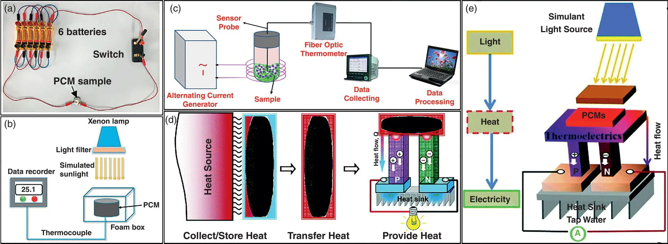
The majorities of the systems used to conduct electro‐to‐heat conversion are organic non‐polymeric solid–liquid PCMs. Leakage‐proof phase change composites composed of microcrystalline cellulose/GNPs aerogel and PEG have been reported. The conductive composites have the ability of electrical energy transition and release ( Figure 2.7a).[95] When an electrical field is applied, electrical energy can be inverted into thermal energy by generating Joule heat. Once the accumulated heat reaches the phase transition temperature of working substance, phase change and heat storage behaviors occur. Likewise, shape‐stabilized PW‐based composites containing commercial melamine foam incorporated by GO and GNPs exhibited high electrical conductivity (2.787 S cm −1) at a filler loading of 4.89 wt% and efficient electro‐to‐heat conversion capacity with an efficiency of 62.5%.[113] In addition, Chen et al.[114] employed solid–solid PCMs to realize electro‐to‐thermal energy conversion. PEG was introduced into graphite foam and then in‐situ polymerized, giving rise to the formation of PU‐based solid–solid phase change composites. When a relatively low voltage of 1.2 or 1.4 V is applied, the phase change composites can complete the electro‐to‐heat conversion, and the estimated conversion efficiency is above 80%. Also, an efficient electro‐to‐heat conversion for PU‐based solid–solid phase change composites has been achieved after introducing electrically conductive graphene aerogel.[115, 116]
2.4.2 Light‐to‐Heat Conversion
Not only can electricity be converted into thermal energy, but also solar energy can be transformed into heat and stored in PCMs. Solar energy, a renewable and clean energy source, is considered to be one of the most effective methods to solve the energy shortage issue. However, there are still technical challenges in the effective utilization of solar energy owing to the intermittence and discontinuity of solar radiation in time and space, which can be exactly solved with the assistance of PCMs storing and releasing heat during the phase transition process. The weak photoabsorption capacity of PCMs makes them unable to convert solar energy into heat directly and effectively. In recent years, dyes,[117] carbon materials (biomass carbon,[118] CNT,[88] EG,[119] graphene,[94] and GO[120]), polydopamine (PDA),[121] Fe 3O 4@graphene,[122] and MXene[70] have been employed as photothermal absorbers for PCMs to realize the efficient conversion and storage of solar energy. The solar‐to‐heat conversion and storage efficiency ( η s) can be calculated from the ratio of the stored heat with respect to the input solar energy according to the light‐thermal calculation Eq. (2.3).
Интервал:
Закладка:
Похожие книги на «Polymer Composites for Electrical Engineering»
Представляем Вашему вниманию похожие книги на «Polymer Composites for Electrical Engineering» списком для выбора. Мы отобрали схожую по названию и смыслу литературу в надежде предоставить читателям больше вариантов отыскать новые, интересные, ещё непрочитанные произведения.


Обсуждение, отзывы о книге «Polymer Composites for Electrical Engineering» и просто собственные мнения читателей. Оставьте ваши комментарии, напишите, что Вы думаете о произведении, его смысле или главных героях. Укажите что конкретно понравилось, а что нет, и почему Вы так считаете.