Gordon Lund - Mercedes E Class Petrol Workshop Manual W210 & W211 Series
Здесь есть возможность читать онлайн «Gordon Lund - Mercedes E Class Petrol Workshop Manual W210 & W211 Series» — ознакомительный отрывок электронной книги совершенно бесплатно, а после прочтения отрывка купить полную версию. В некоторых случаях можно слушать аудио, скачать через торрент в формате fb2 и присутствует краткое содержание. Жанр: unrecognised, на английском языке. Описание произведения, (предисловие) а так же отзывы посетителей доступны на портале библиотеки ЛибКат.

- Название:Mercedes E Class Petrol Workshop Manual W210 & W211 Series
- Автор:
- Жанр:
- Год:неизвестен
- ISBN:нет данных
- Рейтинг книги:5 / 5. Голосов: 1
-
Избранное:Добавить в избранное
- Отзывы:
-
Ваша оценка:
Mercedes E Class Petrol Workshop Manual W210 & W211 Series: краткое содержание, описание и аннотация
Предлагаем к чтению аннотацию, описание, краткое содержание или предисловие (зависит от того, что написал сам автор книги «Mercedes E Class Petrol Workshop Manual W210 & W211 Series»). Если вы не нашли необходимую информацию о книге — напишите в комментариях, мы постараемся отыскать её.
Mercedes E Class Petrol Workshop Manual W210 & W211 Series — читать онлайн ознакомительный отрывок
Ниже представлен текст книги, разбитый по страницам. Система сохранения места последней прочитанной страницы, позволяет с удобством читать онлайн бесплатно книгу «Mercedes E Class Petrol Workshop Manual W210 & W211 Series», без необходимости каждый раз заново искать на чём Вы остановились. Поставьте закладку, и сможете в любой момент перейти на страницу, на которой закончили чтение.
Интервал:
Закладка:
| Std.: | To indicate sizes and limits of components as supplied by the manufacturer. Also to indicate the production tolerances of new unused parts. |
| 0/S | Parts supplied as Oversize or Undersize or recommended limits for such parts, to enable them to be used with worn or re-machined mating parts. |
| U/S | O/S indicates a part that is larger than Std. size U/S may indicate a bore of a bushing or female part that is smaller than Std. |
| Max.: | Where given against a clearance or dimension indicates the maximum allowable lf in excess of the value given it is recommended that the appropriate part is fitted. |
| TIR: | Indicates the Total Indicator Reading as shown by a dial indicator (dial gauge). |
| TDC: | Top Dead Centre (No. 1 piston on firing stroke). |
| MP: | Multi-Purpose grease. |
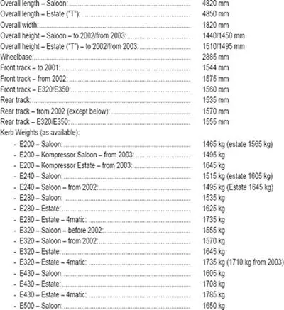
0.3. Dimensions and Weights (typical)
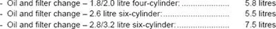
0.4. Capacities
Engines:
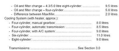
0.5. Jacking up the Vehicle
To prevent damage to the underside of the vehicle, apply a jack or chassis stands only to the points specified below:

Fig. 0.1 – Jacking up the front end of the vehicle. The L.H. view shows where the jack is placed underneath the front crossmember. The R.H. view shows the jacking up of the rear of the vehicle. The jack is placed underneath the centre piece of the rear axle
The front end of the vehicle should be lifted up by placing a jack underneath the transverse crossmember of the front suspension as shown in Fig. 0.1, taking care not to damage the undercover for the engine compartment. To lift the rear end of the vehicle, place the jack underneath the rear axle centre piece, as shown in Fig. 0.1 on the R.H. side. Make sure the jack is sufficient to take the weight of the vehicle. The vehicle can also be jacked up on one side. In this case place the jack underneath the hard rubber inserts near the wheels, as shown in Fig. 0.2 on one side of the vehicle. Never place a jack underneath the oil sump or the gearbox to lift the vehicle.
Fig. 0.2 – Jacking up one side of the vehicle. Place the jack (2) underneath the side of the body as shown. Chassis stands are placed at the position shown.
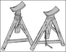
Fig. 0.3 – Three-legged chassis stands are the safest method to support the vehicle when work has to be carried out on the underside of
Chassis stands should only be placed on the L.H. and R.H. sides under the side of the body without damage to the paintwork. Use chassis stands of the construction shown in Fig. 0.3, should be used, but again make sure that they are strong enough to carry the weight of the vehicle. Make sure the vehicle cannot slip off the stands.
Before lifting the front of the vehicle engage first or reverse gear when a manual transmission is fitted or place the gear selector lever into the "P" (park) position when an automatic transmission is fitted. Use suitable chocks and secure the front wheels when the rear end of the vehicle is jacked up.
Always make sure that the ground on which the vehicle is to be jacked up is solid enough to carry the weight of the vehicle.
Note: It is always difficult to raise a vehicle first on one side and then on the other. Take care that the vehicle cannot tip-over when the first side is lifted. Ask a helper to support the vehicle from the other side. Never work underneath the vehicle without adequate support.
0.6. Recommended Tools
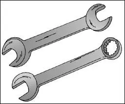
Fig. 0.4 – A double open-ended spanner in the upper view and an open-ended/ring spanner in the lower view. Always make sure that the spanner size is suitable for the nut or bolt to be removed and tightened.
To carry out some of the operations described in the manual you will need some of the tools listed below:
As basic equipment in your tool box you will need a set of open-ended spanners (wrenches) to reach most of the nuts and bolts. A set of ring spanners is also of advantage. To keep the costs as low as possible we recommend a set of combined spanners, open-ended on one side and a ring spanner on the other side. Fig. 0.4 shows a view of the spanners in question. Sockets are also a useful addition to your tool set.
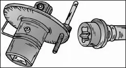
Fig. 0.5 – A graduated disc is used to “angletighten” nuts and bolts. “Torx” head bolts are shown on the R.H. side.
A set of cross-head screwdrivers, pliers and hammers or mallets may also be essential. You will find that many bolts now have a "Torx" head. In case you have never seen a "Torx" head bolt, refer to Fig. 0.5. A socket set with special t "Torx" head inserts is used to slacken and tighten these screws. The size of the bolts are specified by the letter "T" before the across-flat size.
Circlip pliers may also be needed for certain operations. Two types of circlip pliers are available, one type for external circlips, one type for internal circlips. The ends of the pliers can either be straight or angled. Fig. 0.6 shows a view of the circlip pliers. Apart from the circlip pliers you may also need the pliers shown in Fig. 0.7, i.e. side cutters, combination pliers and water pump pliers.
Every part of the vehicle is tightened to a certain torque value and you will therefore need a torque wrench, which can be adjusted to a certain torque setting. In this connection we will also mention a graduated disc, shown in Fig. 0.7, as many parts of the vehicle must be angle-tightened after having been tightened to a specific torque. As some of the angles are not straight forward (for example 30 or 60 degrees), you will either have to estimate the angle or use the disc.
Finally you may consider the tool equipment shown in Fig. 0.8, shown on the next page, which will be necessary from time to time, mainly if you intend to carry out most maintenance and repair jobs yourself.
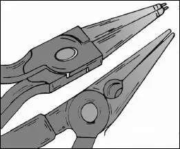
Fig. 0.6 – Circlip pliers are shown in the upper view. The type shown is suitable for outside circlips. The lower view shows a pair ofpointed pliers.
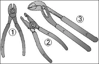
Fig. 0.7 – Assortment of pliers suitable for many operations.
Читать дальшеИнтервал:
Закладка:
Похожие книги на «Mercedes E Class Petrol Workshop Manual W210 & W211 Series»
Представляем Вашему вниманию похожие книги на «Mercedes E Class Petrol Workshop Manual W210 & W211 Series» списком для выбора. Мы отобрали схожую по названию и смыслу литературу в надежде предоставить читателям больше вариантов отыскать новые, интересные, ещё непрочитанные произведения.


Обсуждение, отзывы о книге «Mercedes E Class Petrol Workshop Manual W210 & W211 Series» и просто собственные мнения читателей. Оставьте ваши комментарии, напишите, что Вы думаете о произведении, его смысле или главных героях. Укажите что конкретно понравилось, а что нет, и почему Вы так считаете.