Electromagnetic Vortices
Здесь есть возможность читать онлайн «Electromagnetic Vortices» — ознакомительный отрывок электронной книги совершенно бесплатно, а после прочтения отрывка купить полную версию. В некоторых случаях можно слушать аудио, скачать через торрент в формате fb2 и присутствует краткое содержание. Жанр: unrecognised, на английском языке. Описание произведения, (предисловие) а так же отзывы посетителей доступны на портале библиотеки ЛибКат.
- Название:Electromagnetic Vortices
- Автор:
- Жанр:
- Год:неизвестен
- ISBN:нет данных
- Рейтинг книги:4 / 5. Голосов: 1
-
Избранное:Добавить в избранное
- Отзывы:
-
Ваша оценка:
Electromagnetic Vortices: краткое содержание, описание и аннотация
Предлагаем к чтению аннотацию, описание, краткое содержание или предисловие (зависит от того, что написал сам автор книги «Electromagnetic Vortices»). Если вы не нашли необходимую информацию о книге — напишите в комментариях, мы постараемся отыскать её.
, a team of distinguished researchers delivers a cutting-edge treatment of the research and development of electromagnetic vortex waves, including their related wave properties and several potentially transformative applications.
The book is divided into three parts. The editors first include resources that describe the generation, sorting, and manipulation of vortex waves, as well as descriptions of interesting wave behavior in the infrared and optical regimes with custom-designed nanostructures. They then discuss the generation, multiplexing, and propagation of vortex waves at the microwave and millimeter-wave frequencies. Finally, the selected contributions discuss several representative practical applications of vortex waves from a system perspective.
With coverage that incorporates demonstration examples from a wide range of related sub-areas, this essential edited volume also offers:
Thorough introductions to the generation of optical vortex beams and transformation optical vortex wave synthesizers Comprehensive explorations of millimeter-wave metasurfaces for high-capacity and broadband generation of vector vortex beams, as well as OAM detection and its observation in second harmonic generations Practical discussions of microwave SPP circuits and coding metasurfaces for vortex beam generation and orbital angular momentum-based structured radio beams and their applications In-depth examinations of OAM multiplexing using microwave circuits for near-field communications and wireless power transmission Perfect for students of wireless communications, antenna/RF design, optical communications, and nanophotonics,
is also an indispensable resource for researchers at large defense contractors and government labs.
Electromagnetic Vortices — читать онлайн ознакомительный отрывок
Ниже представлен текст книги, разбитый по страницам. Система сохранения места последней прочитанной страницы, позволяет с удобством читать онлайн бесплатно книгу «Electromagnetic Vortices», без необходимости каждый раз заново искать на чём Вы остановились. Поставьте закладку, и сможете в любой момент перейти на страницу, на которой закончили чтение.
Интервал:
Закладка:
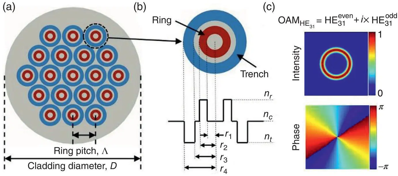
Figure 1.17 (a) Cross‐section of a 19‐ring multi‐OAM multi‐ring fiber. (b) Refractive index profile of a single ring. (c) Intensity and phase distributions of HE 31related OAM mode in a single ring.
Source: Li and Wang [75] © 2014 Springer Nature.
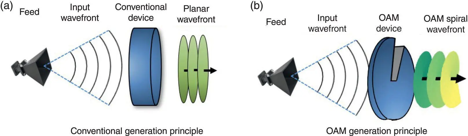
Figure 1.18 Analogy between conventional and OAM generation principle.
The generation of OAM‐carrying beams necessitates the design of antennas that can generate the vortex aperture phase and spiral wavefront that are associated with OAM beams. Some representative designs that have been developed for this purpose are shown in Table 1.1. The spiral phase plate (SPP) has one planar and one spiral surface with a step discontinuity, and the thickness increases as the azimuth angle increases [13, 19,89–91]. The original shape of the conventional parabolic reflector is modified to form a ‘helicoidal reflector’ [23] that converts the field generated by a feed into an OAM‐carrying field [92–94]. A stepped spiral reflecting surface is a discrete approximation of the helicoidal reflector [101]. Planar SPPs, transmitarray [95–100], and reflectarray antennas [5,114–117] employ elements that are distributed in planar surfaces; these elements compensate the phase delay associated with incident waves from different paths emitted from the feed and generate the desired vortex phase distribution. The uniform circular array (UCA) consists of elements that are uniformly distributed on the circumference of a circle. The array elements are fed with an input signal with the same amplitude but with a successive phase delay from element to element such that after a full turn the phase has been incremented by 2π l , where l is the OAM mode number [33, 62,102–109]. The transmittance functions of holographic gratings can also be designed to generate OAM beams [110–113]. Other generation methods include cylindrical lenses [3], spatial light modulators [9], q plates [118], dielectric resonators [119], traveling‐wave circular loops [120], and metasurfaces [121]. The previous designs can generate single‐mode OAM beams, superposition of OAM modes, i.e., mixed‐mode OAM beams [5, 95], and mode‐reconfigurable OAM beams [102, 121].
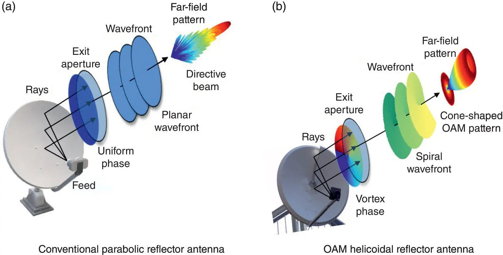
Figure 1.19 Comparison between the generation method of conventional antennas with directive far‐field patterns and OAM antennas: the case of reflector antennas.
1.5 Summary and Perspectives
This chapter has provided a comprehensive overview of OAM beams. We analyzed the fundamental properties of OAM beams and contrasted them with conventional beams. In addition, an appendix is provided to summarize the fundamental mathematical details when the OAM concept is used for potential antenna applications. We discussed emerging applications of OAM in free‐space optical and RF communications as well as in fiber communications, highlighting potentials, and technical challenges. A comprehensive list of relevant references is included. We also summarized the generation methods of optical and RF OAM. Analogies regarding the fundamental properties, antenna communication links, and generation methods between OAM and conventional beams have been provided. More details on various aspects of OAM are discussed in various chapters of this book. We conclude by providing Table 1.2, which summarizes the theoretical and experimental milestones regarding OAM in chronological order. OAM is a field with short history of less than 30 years that has come a long way so far, and we are excited to see the future advancements of OAM.
Table 1.1 OAM generation methods and fabricated prototypes.
| Generation method | Prototype photo | |
|---|---|---|
| Spiral phase plate (SPP) Refs.: [13, 19,89–91] Optical and RF OAM | 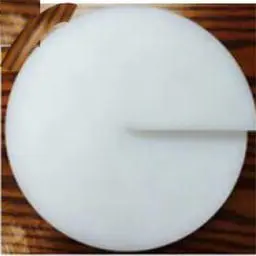 |
Photo credit: [90] |
| Helicoidal reflector antenna and reflector antenna systems Refs. [23,92–94] RF OAM | 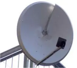 |
Photo credit: [23] |
| Planar spiral phase plate and transmitarray antenna Refs. [95–100] RF OAM | 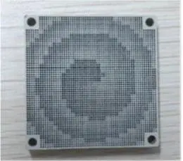 |
Photo credit: [95] |
| Stepped spiral reflecting surface Ref. [101] RF OAM | 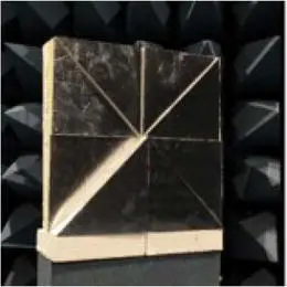 |
Photo credit: [101] |
| Uniform circular array (UCA) Refs. [33, 62,102–109] RF OAM | 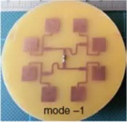 |
Photo credit: [102] |
| Holographic gratings Refs. [110–113] Optical and RF OAM | 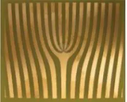 |
Photo credit: [110] |
| Reflectarray antennas Refs. [5,114–117] RF OAM | 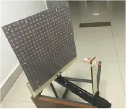 |
Photo credit: [114] |
Appendix 1.A OAM Far-field Calculation
The aperture field of an OAM‐carrying linearly polarized field with a cylindrically symmetric distribution E ( ρ ′) can be written as:
(1.A.1) 
Table 1.2 Chronicle of milestones regarding OAM.
| Reference | Year | Main contribution |
|---|---|---|
| [1] | 1909 | Theoretically studied angular momentum of circularly polarized waves |
| [2] | 1936 | Experimentally studied the SAM of light and demonstrated that SAM can cause the rotation of a mechanical system |
| [3] | 1992 | Recognized that light beams with an azimuthal phase dependence of e jlϕcarrying OAM |
| [17] | 2004 | Conducted the first experiment on OAM free‐space optical communications |
| [76] | 2006 | Reported the generation of an OAM‐carrying optical vortex in optical fibers |
| [62] | 2007 | Numerically showed that OAM can be used in the radio frequency domain |
| [23] | 2012 | Performed the first experimental test of encoding multiple channels on the same radio frequency through OAM |
| [80] | 2013 | Conducted the first OAM‐MDM experiment suggesting that OAM could provide an additional degree of freedom for data multiplexing in future fiber networks |
| [5] | 2018 | Suggested a potential application that takes advantage of the OAM cone‐shaped pattern in the far‐field |
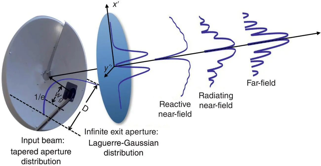
Figure 1.A.1 Schematic of the generation of OAM aperture field.
Читать дальшеИнтервал:
Закладка:
Похожие книги на «Electromagnetic Vortices»
Представляем Вашему вниманию похожие книги на «Electromagnetic Vortices» списком для выбора. Мы отобрали схожую по названию и смыслу литературу в надежде предоставить читателям больше вариантов отыскать новые, интересные, ещё непрочитанные произведения.


Обсуждение, отзывы о книге «Electromagnetic Vortices» и просто собственные мнения читателей. Оставьте ваши комментарии, напишите, что Вы думаете о произведении, его смысле или главных героях. Укажите что конкретно понравилось, а что нет, и почему Вы так считаете.